3X-KKV4S4-65B-R15
60-port sector antenna, 12x 617-960MHz, 24x 1695-2690MHz 65° HPBW and 24x 3300-3800 MHz, 90° HPBW, 15x RET
Features and Benefits
- Separated Extension KIT available for this antenna, check Optional Mounting Kits section
- No pole mounting kit for this antenna
Specifications
General Specifications
| Antenna Type | DualPol® tri-sector |
| Band | Multiband |
| Calibration Connector Interface | M-LOC |
| Calibration Connector Quantity | 3 |
| Color | Light Gray (RAL 7035) |
| Grounding Type | RF connector inner conductor and body grounded to reflector and mounting bracket |
| Performance Note | Outdoor usage |
| Radome Material | Fiberglass, UV resistant |
| Reflector Material | Aluminum |
| RF Connector Interface | 4.3-10 Female | M-LOC |
| RF Connector Location | Bottom |
| RF Connector Quantity, high band | 24 |
| RF Connector Quantity, mid band | 24 |
| RF Connector Quantity, low band | 12 |
| RF Connector Quantity, total | 60 |
Remote Electrical Tilt (RET) Information
| RET Hardware | CommRET v2 |
| RET Interface, quantity | 3 female | 3 male |
| Internal RET | High band (3) | Low band (6) | Mid band (6) |
| Protocol | 3GPP/AISG 2.0 |
Dimensions
| Length | 2100 mm | 82.677 in |
| Outer Diameter | 580 mm | 22.835 in |
Array Layout
| Click on image to enlarge. |

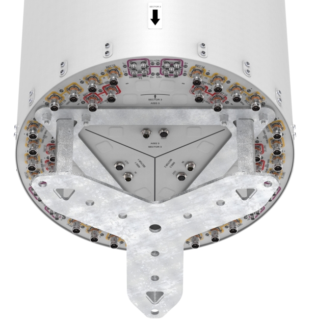
Port Configuration
| Click on image to enlarge. |

Electrical Specifications
| Impedance | 50 ohm |
| Operating Frequency Band | 617 – 960 MHz | 1695 – 2690 MHz | 3300 – 3800 MHz |
| Polarization | ±45° |
| Total Input Power, maximum | 2,400 W |
Electrical Specifications
| R1-R6 | R1-R6 | R1-R6 | R1-R6 | Y1,Y2,Y5,Y6,Y9,YA | Y1,Y2,Y5,Y6,Y9,YA | Y1,Y2,Y5,Y6,Y9,YA | Y3,Y4,Y7,Y8,YB,YC | Y3,Y4,Y7,Y8,YB,YC | Y3,Y4,Y7,Y8,YB,YC | P1-P3 | P1-P3 | |
| Frequency Band, MHz | 617–694 | 694–790 | 790–890 | 890–960 | 1695–1920 | 1920–2180 | 2490–2690 | 1695–1920 | 1920–2180 | 2490–2690 | 3300–3600 | 3600–3800 |
| RF Port | 1-12 | 1-12 | 1-12 | 1-12 | 13,14,19,20,21,22,27,28,29,30,35,36 | 13,14,19,20,21,22,27,28,29,30,35,36 | 13,14,19,20,21,22,27,28,29,30,35,36 | 15-18,23-26,31-34 | 15-18,23-26,31-34 | 15-18,23-26,31-34 | 37-60 | 37-60 |
| Beamwidth, Horizontal, degrees | 71 | 62 | 56 | 52 | 73 | 63 | 56 | 65 | 60 | 55 | 84 | 82 |
| Beamwidth, Vertical, degrees | 11.9 | 10.9 | 9.8 | 9.1 | 7.9 | 7.1 | 5.7 | 7.9 | 7 | 5.7 | 6.4 | 6 |
| Beam Tilt, degrees | 2–12 | 2–12 | 2–12 | 2–12 | 2–12 | 2–12 | 2–12 | 2–12 | 2–12 | 2–12 | 2–12 | 2–12 |
| USLS (First Lobe), dB | 15 | 16 | 16 | 15 | 17 | 18 | 17 | 15 | 19 | 19 | 14 | 15 |
| Front-to-Back Total Power at 180° ± 30°, dB | 20 | 21 | 22 | 22 | 24 | 23 | 22 | 24 | 27 | 24 | 22 | 23 |
| Coupling level, Amp, Antenna port to Cal port, dB | 26 | 26 | ||||||||||
| Coupling level, max Amp Δ, Antenna port to Cal port, dB | ±2 | ±2 | ||||||||||
| Coupler, max Amp Δ, Antenna port to Cal port, dB | 0.9 | 0.9 | ||||||||||
| Coupler, max Phase Δ, Antenna port to Cal port, degrees | 7 | 7 | ||||||||||
| Isolation, Cross Polarization, dB | 25 | 25 | 25 | 25 | 25 | 25 | 25 | 25 | 25 | 25 | 25 | 25 |
| Isolation, Inter-band, dB | 25 | 25 | 25 | 25 | 25 | 25 | 25 | 25 | 25 | 25 | 25 | 25 |
| Isolation, Co-polarization, dB | 19 | 19 | ||||||||||
| VSWR | Return loss, dB | 1.5 | 14.0 | 1.5 | 14.0 | 1.5 | 14.0 | 1.5 | 14.0 | 1.5 | 14.0 | 1.5 | 14.0 | 1.5 | 14.0 | 1.5 | 14.0 | 1.5 | 14.0 | 1.5 | 14.0 | 1.5 | 14.0 | 1.5 | 14.0 |
| PIM, 3rd Order, typical, 2 x 20 W, dBc | -153 | -153 | -153 | -153 | -153 | -153 | -153 | -153 | -153 | -153 | -145 | -145 |
| Input Power per Port at 50°C, maximum, watts | 250 | 250 | 250 | 250 | 200 | 200 | 150 | 200 | 200 | 150 | 75 | 75 |
Electrical Specifications, BASTA
| Frequency Band, MHz | 617–694 | 694–790 | 790–890 | 890–960 | 1695–1920 | 1920–2180 | 2490–2690 | 1695–1920 | 1920–2180 | 2490–2690 | 3300–3600 | 3600–3800 |
| Gain by all Beam Tilts, average, dBi | 13.0 | 13.6 | 14.3 | 14.8 | 15.6 | 16.5 | 17.1 | 15.2 | 16.3 | 17.0 | 14.8 | 15.2 |
Electrical Specifications, Broadcast 65
| Frequency Band, MHz | 617–694 | 694–790 | 790–890 | 890–960 | 1695–1920 | 1920–2180 | 2490–2690 | 1695–1920 | 1920–2180 | 2490–2690 | 3300–3600 | 3600–3800 |
| Gain, dBi | 16.6 | 16.4 | ||||||||||
| Beamwidth, Horizontal, degrees | 65 | 65 | ||||||||||
| Beamwidth, Horizontal at 10 dB, degrees | 115 | 110 | ||||||||||
| Beamwidth, Vertical, degrees | 6.2 | 6.1 | ||||||||||
| Front-to-Back Total Power at 180° ± 30°, dB | 25 | 25 | ||||||||||
| USLS (First Lobe), dB | 18 | 21 |
Electrical Specifications, Service Beam
| Frequency Band, MHz | 617–694 | 694–790 | 790–890 | 890–960 | 1695–1920 | 1920–2180 | 2490–2690 | 1695–1920 | 1920–2180 | 2490–2690 | 3300–3600 | 3600–3800 |
| Steered 0° Gain, dBi | 19.9 | 20.6 | ||||||||||
| Steered 0° Beamwidth, Horizontal, degrees | 26 | 24 | ||||||||||
| Steered 0° Front-to-Back Total Power at 180° ± 30°, dB | 28 | 31 | ||||||||||
| Steered 30° Gain, dBi | 19.3 | 19.3 | ||||||||||
| Steered 30° Beamwidth, Horizontal, degrees | 29 | 29 | ||||||||||
| Steered 30° Front-to-Back Total Power at 180° ± 30°, dB | 36 | 35 |
Electrical Specifications, Soft Split
| Frequency Band, MHz | 617–694 | 694–790 | 790–890 | 890–960 | 1695–1920 | 1920–2180 | 2490–2690 | 1695–1920 | 1920–2180 | 2490–2690 | 3300–3600 | 3600–3800 |
| Gain, dBi | 19.1 | 19.3 | ||||||||||
| Beamwidth, Horizontal, degrees | 32 | 31 | ||||||||||
| Front-to-Back Total Power at 180° ± 30°, dB | 27 | 28 | ||||||||||
| Horizontal Sidelobe, dB | 16 | 19 |
Mechanical Specifications
| Wind Loading @ Velocity, frontal | 745.0 N @ 150 km/h (167.5 lbf @ 150 km/h) |
| Wind Loading @ Velocity, lateral | 745.0 N @ 150 km/h (167.5 lbf @ 150 km/h) |
| Wind Loading @ Velocity, maximum | 745.0 N @ 150 km/h (167.5 lbf @ 150 km/h) |
| Wind Loading @ Velocity, rear | 745.0 N @ 150 km/h (167.5 lbf @ 150 km/h) |
| Wind Speed, maximum | 241 km/h (150 mph) |
Packaging and Weights
| Width, packed | 714 mm | 28.110 in |
| Depth, packed | 692 mm | 27.244 in |
| Length, packed | 2537 mm | 99.882 in |
| Weight, gross | 120 kg | 264.554 lb |
Regulatory Compliance/Certifications
| Agency | Classification |
| ISO 9001:2015 | Designed, manufactured and/or distributed under this quality management system |
General Specifications
| Antenna Type | DualPol® tri-sector |
| Band | Multiband |
| Calibration Connector Interface | M-LOC |
| Calibration Connector Quantity | 3 |
| Color | Light Gray (RAL 7035) |
| Grounding Type | RF connector inner conductor and body grounded to reflector and mounting bracket |
| Performance Note | Outdoor usage |
| Radome Material | Fiberglass, UV resistant |
| Reflector Material | Aluminum |
| RF Connector Interface | 4.3-10 Female | M-LOC |
| RF Connector Location | Bottom |
| RF Connector Quantity, high band | 24 |
| RF Connector Quantity, mid band | 24 |
| RF Connector Quantity, low band | 12 |
| RF Connector Quantity, total | 60 |
Remote Electrical Tilt (RET) Information
| RET Hardware | CommRET v2 |
| RET Interface, quantity | 3 female | 3 male |
| Internal RET | High band (3) | Low band (6) | Mid band (6) |
| Protocol | 3GPP/AISG 2.0 |
Dimensions
| Length | 2100 mm | 82.677 in |
| Outer Diameter | 580 mm | 22.835 in |
Electrical Specifications
| Impedance | 50 ohm |
| Operating Frequency Band | 617 – 960 MHz | 1695 – 2690 MHz | 3300 – 3800 MHz |
| Polarization | ±45° |
| Total Input Power, maximum | 2,400 W |
Electrical Specifications
| R1-R6 | R1-R6 | R1-R6 | R1-R6 | Y1,Y2,Y5,Y6,Y9,YA | Y1,Y2,Y5,Y6,Y9,YA | Y1,Y2,Y5,Y6,Y9,YA | Y3,Y4,Y7,Y8,YB,YC | Y3,Y4,Y7,Y8,YB,YC | Y3,Y4,Y7,Y8,YB,YC | P1-P3 | P1-P3 | |
| Frequency Band, MHz | 617–694 | 694–790 | 790–890 | 890–960 | 1695–1920 | 1920–2180 | 2490–2690 | 1695–1920 | 1920–2180 | 2490–2690 | 3300–3600 | 3600–3800 |
| RF Port | 1-12 | 1-12 | 1-12 | 1-12 | 13,14,19,20,21,22,27,28,29,30,35,36 | 13,14,19,20,21,22,27,28,29,30,35,36 | 13,14,19,20,21,22,27,28,29,30,35,36 | 15-18,23-26,31-34 | 15-18,23-26,31-34 | 15-18,23-26,31-34 | 37-60 | 37-60 |
| Beamwidth, Horizontal, degrees | 71 | 62 | 56 | 52 | 73 | 63 | 56 | 65 | 60 | 55 | 84 | 82 |
| Beamwidth, Vertical, degrees | 11.9 | 10.9 | 9.8 | 9.1 | 7.9 | 7.1 | 5.7 | 7.9 | 7 | 5.7 | 6.4 | 6 |
| Beam Tilt, degrees | 2–12 | 2–12 | 2–12 | 2–12 | 2–12 | 2–12 | 2–12 | 2–12 | 2–12 | 2–12 | 2–12 | 2–12 |
| USLS (First Lobe), dB | 15 | 16 | 16 | 15 | 17 | 18 | 17 | 15 | 19 | 19 | 14 | 15 |
| Front-to-Back Total Power at 180° ± 30°, dB | 20 | 21 | 22 | 22 | 24 | 23 | 22 | 24 | 27 | 24 | 22 | 23 |
| Coupling level, Amp, Antenna port to Cal port, dB | 26 | 26 | ||||||||||
| Coupling level, max Amp Δ, Antenna port to Cal port, dB | ±2 | ±2 | ||||||||||
| Coupler, max Amp Δ, Antenna port to Cal port, dB | 0.9 | 0.9 | ||||||||||
| Coupler, max Phase Δ, Antenna port to Cal port, degrees | 7 | 7 | ||||||||||
| Isolation, Cross Polarization, dB | 25 | 25 | 25 | 25 | 25 | 25 | 25 | 25 | 25 | 25 | 25 | 25 |
| Isolation, Inter-band, dB | 25 | 25 | 25 | 25 | 25 | 25 | 25 | 25 | 25 | 25 | 25 | 25 |
| Isolation, Co-polarization, dB | 19 | 19 | ||||||||||
| VSWR | Return loss, dB | 1.5 | 14.0 | 1.5 | 14.0 | 1.5 | 14.0 | 1.5 | 14.0 | 1.5 | 14.0 | 1.5 | 14.0 | 1.5 | 14.0 | 1.5 | 14.0 | 1.5 | 14.0 | 1.5 | 14.0 | 1.5 | 14.0 | 1.5 | 14.0 |
| PIM, 3rd Order, typical, 2 x 20 W, dBc | -153 | -153 | -153 | -153 | -153 | -153 | -153 | -153 | -153 | -153 | -145 | -145 |
| Input Power per Port at 50°C, maximum, watts | 250 | 250 | 250 | 250 | 200 | 200 | 150 | 200 | 200 | 150 | 75 | 75 |
Electrical Specifications, BASTA
| Frequency Band, MHz | 617–694 | 694–790 | 790–890 | 890–960 | 1695–1920 | 1920–2180 | 2490–2690 | 1695–1920 | 1920–2180 | 2490–2690 | 3300–3600 | 3600–3800 |
| Gain by all Beam Tilts, average, dBi | 13.0 | 13.6 | 14.3 | 14.8 | 15.6 | 16.5 | 17.1 | 15.2 | 16.3 | 17.0 | 14.8 | 15.2 |
Electrical Specifications, Broadcast 65
| Frequency Band, MHz | 617–694 | 694–790 | 790–890 | 890–960 | 1695–1920 | 1920–2180 | 2490–2690 | 1695–1920 | 1920–2180 | 2490–2690 | 3300–3600 | 3600–3800 |
| Gain, dBi | 16.6 | 16.4 | ||||||||||
| Beamwidth, Horizontal, degrees | 65 | 65 | ||||||||||
| Beamwidth, Horizontal at 10 dB, degrees | 115 | 110 | ||||||||||
| Beamwidth, Vertical, degrees | 6.2 | 6.1 | ||||||||||
| Front-to-Back Total Power at 180° ± 30°, dB | 25 | 25 | ||||||||||
| USLS (First Lobe), dB | 18 | 21 |
Electrical Specifications, Service Beam
| Frequency Band, MHz | 617–694 | 694–790 | 790–890 | 890–960 | 1695–1920 | 1920–2180 | 2490–2690 | 1695–1920 | 1920–2180 | 2490–2690 | 3300–3600 | 3600–3800 |
| Steered 0° Gain, dBi | 19.9 | 20.6 | ||||||||||
| Steered 0° Beamwidth, Horizontal, degrees | 26 | 24 | ||||||||||
| Steered 0° Front-to-Back Total Power at 180° ± 30°, dB | 28 | 31 | ||||||||||
| Steered 30° Gain, dBi | 19.3 | 19.3 | ||||||||||
| Steered 30° Beamwidth, Horizontal, degrees | 29 | 29 | ||||||||||
| Steered 30° Front-to-Back Total Power at 180° ± 30°, dB | 36 | 35 |
Electrical Specifications, Soft Split
| Frequency Band, MHz | 617–694 | 694–790 | 790–890 | 890–960 | 1695–1920 | 1920–2180 | 2490–2690 | 1695–1920 | 1920–2180 | 2490–2690 | 3300–3600 | 3600–3800 |
| Gain, dBi | 19.1 | 19.3 | ||||||||||
| Beamwidth, Horizontal, degrees | 32 | 31 | ||||||||||
| Front-to-Back Total Power at 180° ± 30°, dB | 27 | 28 | ||||||||||
| Horizontal Sidelobe, dB | 16 | 19 |
Mechanical Specifications
| Wind Loading @ Velocity, frontal | 745.0 N @ 150 km/h (167.5 lbf @ 150 km/h) |
| Wind Loading @ Velocity, lateral | 745.0 N @ 150 km/h (167.5 lbf @ 150 km/h) |
| Wind Loading @ Velocity, maximum | 745.0 N @ 150 km/h (167.5 lbf @ 150 km/h) |
| Wind Loading @ Velocity, rear | 745.0 N @ 150 km/h (167.5 lbf @ 150 km/h) |
| Wind Speed, maximum | 241 km/h (150 mph) |
Packaging and Weights
| Width, packed | 714 mm | 28.110 in |
| Depth, packed | 692 mm | 27.244 in |
| Length, packed | 2537 mm | 99.882 in |
| Weight, gross | 120 kg | 264.554 lb |
| Click on image to enlarge. |
| Click on image to enlarge. |
Regulatory Compliance/Certifications
| Agency | Classification |
| ISO 9001:2015 | Designed, manufactured and/or distributed under this quality management system |
Documentation & Downloads
Assembly Drawing
Installation Instruction
Product Information
Product Specification
Warranty
Assembly Drawing
Installation Instruction
Product Compliance Documentation
Product Information
Product Specification
Warranty
Other Ways to Browse
