E14F20P14
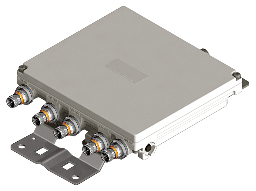
Ultra Compact Single Pentaplexer 700-900/1400-1800/2100/2300-2600/3300-3800, dc bypass on low band, with 4.3-10 connectors
Features and Benefits
- New Combining Solution to introduce 5G, 3.5GHz band
- Industry leading PIM performance
- New 4.3-10 connectors for improved PIM performance and size reduction
- Suitable for feeders cables reduction
- Single configuration
Specifications
Product Classification
| Product Type | Pentaplexer |
General Specifications
| Color | Gray |
| Modularity | 1-Single |
| Mounting | Pole | Wall |
| Mounting Pipe Hardware | Band clamps (2) |
| RF Connector Interface | 4.3-10 Female |
| RF Connector Interface Body Style | Medium neck |
Dimensions
| Height | 58.5 mm | 2.303 in |
| Width | 227 mm | 8.937 in |
| Depth | 204 mm | 8.032 in |
| Mounting Pipe Diameter Range | 43–122 mm |
Outline Drawing
| Click on image to enlarge. |

Electrical Specifications
| Impedance | 50 ohm |
| License Band, Band Pass | APT 700 | CEL 850 | CEL 900 | DCS 1800 | EDD 800 | IMT 2100 | IMT 2600 | LMR 800 | LMR 900 | SDL 1400 | TDD 2300 | TDD 2600 | TDD 3500 | USA 700 | WCS 2300 |
Electrical Specifications, dc Power/Alarm
| dc/AISG Pass-through Method | Factory set |
| dc/AISG Pass-through, combiner | Branch 1 |
| dc/AISG Pass-through, demultiplexer | Branch 1 |
| Lightning Surge Current | 5 kA |
| Lightning Surge Current Waveform | 8/20 waveform |
Electrical Specifications, AISG
| AISG Carrier | 2176 KHz ± 100 ppm |
| AISG Pass-through Current, maximum | 2.5 A |
| Insertion Loss, maximum | 0.5 dB |
Electrical Specifications
| Sub-module | 1 | 2 | 1 | 2 | 1 | 2 | 1 | 2 | 1 | 2 |
| Branch | 1 | 2 | 3 | 4 | 5 |
| Port Designation | PORT 1 698-960 | PORT 2 1350-1880 | PORT 3 1920-2200 | PORT 4 2300-2690 | PORT 5 3300-3800 |
| License Band | APT 700, Band Pass CEL 850, Band Pass CEL 900, Band Pass EDD 800, Band Pass LMR 800, Band Pass LMR 900, Band Pass USA 700, Band Pass | DCS 1800, Band Pass SDL 1400, Band Pass | IMT 2100, Band Pass | IMT 2600, Band Pass TDD 2300, Band Pass TDD 2600, Band Pass WCS 2300, Band Pass | TDD 3500, Band Pass |
Electrical Specifications, Band Pass
| Frequency Range, MHz | 698–960 | 1350–1525 1710–1880 | 1920–2200 | 2300–2690 | 3300–3800 |
| Insertion Loss, typical, dB | 0.30 | 0.30 | 0.30 | 0.25 | 0.20 |
| Return Loss, typical, dB | 20 | 20 | 20 | 20 | 16 |
| Isolation, typical, dB | 52 | 52 | 52 | 52 | 52 |
| Input Power, RMS, maximum, W | 100 | 100 | 100 | 100 | 100 |
| Input Power, PEP, maximum, W | 1,000 | 1,000 | 1,000 | 1,000 | 1,000 |
| 3rd Order PIM, typical, dBc | -163 | -163 | -163 | -163 | -163 |
| 3rd Order PIM Test Method | Two +43 dBm carriers | Two +43 dBm carriers | Two +43 dBm carriers | Two +43 dBm carriers | Two +43 dBm carriers |
Block Diagram
| Click on image to enlarge. |

Mechanical Specifications
| Wind Speed, maximum | 240 km/h (149 mph) |
Environmental Specifications
| Operating Temperature | -40 °C to +65 °C (-40 °F to +149 °F) |
| Corrosion Test Method | IEC 60068-2-11, 30 days |
| Environmental Test Method | ETSI EN 300 019-1-4 |
| Ingress Protection Test Method | IEC 60529:2001, IP67 |
| Vibration Test Method | IEC 60068-2-6 |
Packaging and Weights
| Included | Mounting hardware |
| Volume | 2.7 L |
| Weight, net | 3.7 kg | 8.157 lb |
| Weight, without mounting hardware | 3.2 kg | 7.055 lb |
Product Classification
| Product Type | Pentaplexer |
General Specifications
| Color | Gray |
| Modularity | 1-Single |
| Mounting | Pole | Wall |
| Mounting Pipe Hardware | Band clamps (2) |
| RF Connector Interface | 4.3-10 Female |
| RF Connector Interface Body Style | Medium neck |
Dimensions
| Height | 58.5 mm | 2.303 in |
| Width | 227 mm | 8.937 in |
| Depth | 204 mm | 8.032 in |
| Mounting Pipe Diameter Range | 43–122 mm |
Electrical Specifications
| Impedance | 50 ohm |
| License Band, Band Pass | APT 700 | CEL 850 | CEL 900 | DCS 1800 | EDD 800 | IMT 2100 | IMT 2600 | LMR 800 | LMR 900 | SDL 1400 | TDD 2300 | TDD 2600 | TDD 3500 | USA 700 | WCS 2300 |
Electrical Specifications, dc Power/Alarm
| dc/AISG Pass-through Method | Factory set |
| dc/AISG Pass-through, combiner | Branch 1 |
| dc/AISG Pass-through, demultiplexer | Branch 1 |
| Lightning Surge Current | 5 kA |
| Lightning Surge Current Waveform | 8/20 waveform |
Electrical Specifications, AISG
| AISG Carrier | 2176 KHz ± 100 ppm |
| AISG Pass-through Current, maximum | 2.5 A |
| Insertion Loss, maximum | 0.5 dB |
Electrical Specifications
| Sub-module | 1 | 2 | 1 | 2 | 1 | 2 | 1 | 2 | 1 | 2 |
| Branch | 1 | 2 | 3 | 4 | 5 |
| Port Designation | PORT 1 698-960 | PORT 2 1350-1880 | PORT 3 1920-2200 | PORT 4 2300-2690 | PORT 5 3300-3800 |
| License Band | APT 700, Band Pass; CEL 850, Band Pass; CEL 900, Band Pass; EDD 800, Band Pass; LMR 800, Band Pass; LMR 900, Band Pass; USA 700, Band Pass | DCS 1800, Band Pass; SDL 1400, Band Pass | IMT 2100, Band Pass | IMT 2600, Band Pass; TDD 2300, Band Pass; TDD 2600, Band Pass; WCS 2300, Band Pass | TDD 3500, Band Pass |
Electrical Specifications, Band Pass
| Frequency Range, MHz | 698–960 | 1350–1525; 1710–1880 | 1920–2200 | 2300–2690 | 3300–3800 |
| Insertion Loss, typical, dB | 0.30 | 0.30 | 0.30 | 0.25 | 0.20 |
| Return Loss, typical, dB | 20 | 20 | 20 | 20 | 16 |
| Isolation, typical, dB | 52 | 52 | 52 | 52 | 52 |
| Input Power, RMS, maximum, W | 100 | 100 | 100 | 100 | 100 |
| Input Power, PEP, maximum, W | 1,000 | 1,000 | 1,000 | 1,000 | 1,000 |
| 3rd Order PIM, typical, dBc | -163 | -163 | -163 | -163 | -163 |
| 3rd Order PIM Test Method | Two +43 dBm carriers | Two +43 dBm carriers | Two +43 dBm carriers | Two +43 dBm carriers | Two +43 dBm carriers |
Mechanical Specifications
| Wind Speed, maximum | 240 km/h (149 mph) |
Environmental Specifications
| Operating Temperature | -40 °C to +65 °C (-40 °F to +149 °F) |
| Corrosion Test Method | IEC 60068-2-11, 30 days |
| Environmental Test Method | ETSI EN 300 019-1-4 |
| Ingress Protection Test Method | IEC 60529:2001, IP67 |
| Vibration Test Method | IEC 60068-2-6 |
Packaging and Weights
| Included | Mounting hardware |
| Volume | 2.7 L |
| Weight, net | 3.7 kg | 8.157 lb |
| Weight, without mounting hardware | 3.2 kg | 7.055 lb |
| Click on image to enlarge. |
| Click on image to enlarge. |
Documentation & Downloads
Installation Instruction
Product Specification
Video
Filter Products – Designed for PIM Excellence

Filter Products – Designed for PIM Excellence
Warranty
Installation Instruction
Product Compliance Documentation
Product Specification
Video
Filter Products – Designed for PIM Excellence
Filter Products – Designed for PIM Excellence
Warranty
Other Ways to Browse
