RRVV-65D-R6D
8-port sector antenna, 4x 694–960, 4x 1695–2180/ 2490–2690 MHz, 65° HPBW , 6x RET
Features and Benefits
- All Internal RET actuators are connected in “Cascaded SRET” configuration
- Internal SBT on low and high band allow remote RET control from the radio over the RF jumper cable
- Utilize new aerodynamic endcap for wind load optimization
Specifications
General Specifications
| Antenna Type | Sector |
| Band | Multiband |
| Color | Light Gray (RAL 7035) |
| Grounding Type | RF connector inner conductor and body grounded to reflector and mounting bracket |
| Performance Note | Outdoor usage |
| Radome Material | Fiberglass, UV resistant |
| Reflector Material | Aluminum |
| RF Connector Interface | 4.3-10 Female |
| RF Connector Location | Bottom |
| RF Connector Quantity, high band | 4 |
| RF Connector Quantity, low band | 4 |
| RF Connector Quantity, total | 8 |
Remote Electrical Tilt (RET) Information
| RET Hardware | CommRET v2 |
| RET Interface | 8-pin DIN Female | 8-pin DIN Male |
| RET Interface, quantity | 2 female | 2 male |
| Input Voltage | 10–30 Vdc |
| Internal Bias Tee | Port 1 | Port 5 |
| Internal RET | High band (4) | Low band (2) |
| Power Consumption, active state, maximum | 8 W |
| Power Consumption, idle state, maximum | 1 W |
| Protocol | 3GPP/AISG 2.0 |
Dimensions
| Width | 498 mm | 19.606 in |
| Depth | 197 mm | 7.756 in |
| Length | 2688 mm | 105.827 in |
| Net Weight, antenna only | 52 kg | 114.640 lb |
Array Layout
| Click on image to enlarge. |

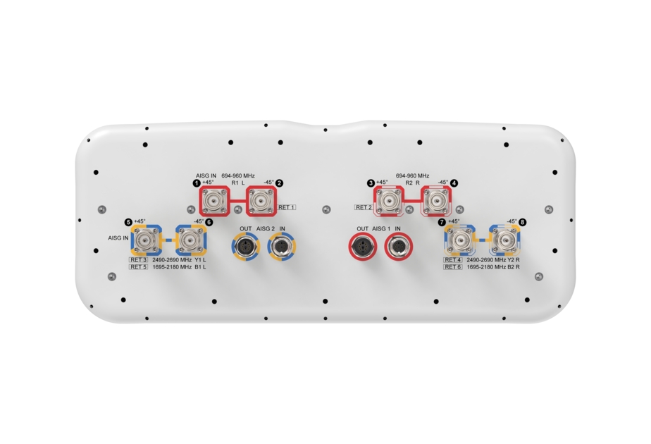
Port Configuration
| Click on image to enlarge. |

Electrical Specifications
| Impedance | 50 ohm |
| Operating Frequency Band | 694 – 960 MHz | 1695 – 2180 MHz | 2490 – 2690 MHz |
| Polarization | ±45° |
Electrical Specifications
| R1,R2 | R1,R2 | R1,R2 | Y1,Y2,B1,B2 | Y1,Y2,B1,B2 | Y1,Y2,B1,B2 | |
| Frequency Band, MHz | 694–790 | 790–890 | 880–960 | 1695–1920 | 1920–2180 | 2490–2690 |
| RF Port | 1,2,3,4 | 1,2,3,4 | 1,2,3,4 | 5,6,7,8 | 5,6,7,8 | 5,6,7,8 |
| Gain, dBi | 15.7 | 16.1 | 16.6 | 16.5 | 16.6 | 16.4 |
| Beamwidth, Horizontal, degrees | 77 | 67 | 68 | 58 | 62 | 68 |
| Beamwidth, Vertical, degrees | 7.4 | 6.6 | 6.2 | 6.8 | 6.1 | 5.1 |
| Beam Tilt, degrees | 1–11 | 1–11 | 1–11 | 0–10 | 0–10 | 0–10 |
| USLS (First Lobe), dB | 16 | 16 | 20 | 18 | 18 | 17 |
| Front-to-Back Ratio at 180°, dB | 29 | 30 | 32 | 34 | 34 | 25 |
| Isolation, Cross Polarization, dB | 26 | 26 | 26 | 26 | 26 | 26 |
| Isolation, Inter-band, dB | 28 | 28 | 28 | 28 | 28 | 28 |
| VSWR | Return loss, dB | 1.5 | 14.0 | 1.5 | 14.0 | 1.5 | 14.0 | 1.5 | 14.0 | 1.5 | 14.0 | 1.5 | 14.0 |
| PIM, 3rd Order, 2 x 20 W, dBc | -150 | -150 | -150 | -150 | -150 | -150 |
| Input Power per Port at 50°C, maximum, watts | 300 | 300 | 300 | 250 | 250 | 200 |
Packaging and Weights
| Width, packed | 565 mm | 22.244 in |
| Depth, packed | 309 mm | 12.165 in |
| Length, packed | 2935 mm | 115.551 in |
| Weight, gross | 72.9 kg | 160.717 lb |
Regulatory Compliance/Certifications
| Agency | Classification |
| ISO 9001:2015 | Designed, manufactured and/or distributed under this quality management system |
General Specifications
| Antenna Type | Sector |
| Band | Multiband |
| Color | Light Gray (RAL 7035) |
| Grounding Type | RF connector inner conductor and body grounded to reflector and mounting bracket |
| Performance Note | Outdoor usage |
| Radome Material | Fiberglass, UV resistant |
| Reflector Material | Aluminum |
| RF Connector Interface | 4.3-10 Female |
| RF Connector Location | Bottom |
| RF Connector Quantity, high band | 4 |
| RF Connector Quantity, low band | 4 |
| RF Connector Quantity, total | 8 |
Remote Electrical Tilt (RET) Information
| RET Hardware | CommRET v2 |
| RET Interface | 8-pin DIN Female | 8-pin DIN Male |
| RET Interface, quantity | 2 female | 2 male |
| Input Voltage | 10–30 Vdc |
| Internal Bias Tee | Port 1 | Port 5 |
| Internal RET | High band (4) | Low band (2) |
| Power Consumption, active state, maximum | 8 W |
| Power Consumption, idle state, maximum | 1 W |
| Protocol | 3GPP/AISG 2.0 |
Dimensions
| Width | 498 mm | 19.606 in |
| Depth | 197 mm | 7.756 in |
| Length | 2688 mm | 105.827 in |
| Net Weight, antenna only | 52 kg | 114.640 lb |
Electrical Specifications
| Impedance | 50 ohm |
| Operating Frequency Band | 694 – 960 MHz | 1695 – 2180 MHz | 2490 – 2690 MHz |
| Polarization | ±45° |
Electrical Specifications
| R1,R2 | R1,R2 | R1,R2 | Y1,Y2,B1,B2 | Y1,Y2,B1,B2 | Y1,Y2,B1,B2 | |
| Frequency Band, MHz | 694–790 | 790–890 | 880–960 | 1695–1920 | 1920–2180 | 2490–2690 |
| RF Port | 1,2,3,4 | 1,2,3,4 | 1,2,3,4 | 5,6,7,8 | 5,6,7,8 | 5,6,7,8 |
| Gain, dBi | 15.7 | 16.1 | 16.6 | 16.5 | 16.6 | 16.4 |
| Beamwidth, Horizontal, degrees | 77 | 67 | 68 | 58 | 62 | 68 |
| Beamwidth, Vertical, degrees | 7.4 | 6.6 | 6.2 | 6.8 | 6.1 | 5.1 |
| Beam Tilt, degrees | 1–11 | 1–11 | 1–11 | 0–10 | 0–10 | 0–10 |
| USLS (First Lobe), dB | 16 | 16 | 20 | 18 | 18 | 17 |
| Front-to-Back Ratio at 180°, dB | 29 | 30 | 32 | 34 | 34 | 25 |
| Isolation, Cross Polarization, dB | 26 | 26 | 26 | 26 | 26 | 26 |
| Isolation, Inter-band, dB | 28 | 28 | 28 | 28 | 28 | 28 |
| VSWR | Return loss, dB | 1.5 | 14.0 | 1.5 | 14.0 | 1.5 | 14.0 | 1.5 | 14.0 | 1.5 | 14.0 | 1.5 | 14.0 |
| PIM, 3rd Order, 2 x 20 W, dBc | -150 | -150 | -150 | -150 | -150 | -150 |
| Input Power per Port at 50°C, maximum, watts | 300 | 300 | 300 | 250 | 250 | 200 |
Packaging and Weights
| Width, packed | 565 mm | 22.244 in |
| Depth, packed | 309 mm | 12.165 in |
| Length, packed | 2935 mm | 115.551 in |
| Weight, gross | 72.9 kg | 160.717 lb |
| Click on image to enlarge. |
| Click on image to enlarge. |
Regulatory Compliance/Certifications
| Agency | Classification |
| ISO 9001:2015 | Designed, manufactured and/or distributed under this quality management system |
Documentation & Downloads
Assembly Drawing
Product Information
Product Specification
Assembly Drawing
Product Compliance Documentation
Product Information
Product Specification
Related Products and Accessories
Included Products
Antennas
-
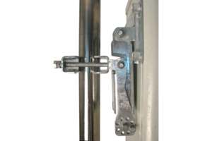
![]() BSAMNT-4 Wide Profile Antenna Downtilt Mounting Kit for 2.4 - 4.5 in (60 - 115 mm) OD round members. Kit contains one scissor top bracket set and one bottom bracket set.
BSAMNT-4 Wide Profile Antenna Downtilt Mounting Kit for 2.4 - 4.5 in (60 - 115 mm) OD round members. Kit contains one scissor top bracket set and one bottom bracket set. -
![]() BSAMNT-M4 Middle Downtilt Mounting Kit for Long Antennas for 2.4 - 4.5 in (60 - 115 mm) OD round members. Kit contains one scissor bracket set.
BSAMNT-M4 Middle Downtilt Mounting Kit for Long Antennas for 2.4 - 4.5 in (60 - 115 mm) OD round members. Kit contains one scissor bracket set.
Structural Support, Tools & Accessories
-
![]() BSAMNT-4 Wide Profile Antenna Downtilt Mounting Kit for 2.4 - 4.5 in (60 - 115 mm) OD round members. Kit contains one scissor top bracket set and one bottom bracket set.
BSAMNT-4 Wide Profile Antenna Downtilt Mounting Kit for 2.4 - 4.5 in (60 - 115 mm) OD round members. Kit contains one scissor top bracket set and one bottom bracket set. -
![]() BSAMNT-M4 Middle Downtilt Mounting Kit for Long Antennas for 2.4 - 4.5 in (60 - 115 mm) OD round members. Kit contains one scissor bracket set.
BSAMNT-M4 Middle Downtilt Mounting Kit for Long Antennas for 2.4 - 4.5 in (60 - 115 mm) OD round members. Kit contains one scissor bracket set.
Included Products
Antennas
-
![]() BSAMNT-4 Wide Profile Antenna Downtilt Mounting Kit for 2.4 - 4.5 in (60 - 115 mm) OD round members. Kit contains one scissor top bracket set and one bottom bracket set.
BSAMNT-4 Wide Profile Antenna Downtilt Mounting Kit for 2.4 - 4.5 in (60 - 115 mm) OD round members. Kit contains one scissor top bracket set and one bottom bracket set. -
![]() BSAMNT-M4 Middle Downtilt Mounting Kit for Long Antennas for 2.4 - 4.5 in (60 - 115 mm) OD round members. Kit contains one scissor bracket set.
BSAMNT-M4 Middle Downtilt Mounting Kit for Long Antennas for 2.4 - 4.5 in (60 - 115 mm) OD round members. Kit contains one scissor bracket set.
Structural Support, Tools & Accessories
-
![]() BSAMNT-4 Wide Profile Antenna Downtilt Mounting Kit for 2.4 - 4.5 in (60 - 115 mm) OD round members. Kit contains one scissor top bracket set and one bottom bracket set.
BSAMNT-4 Wide Profile Antenna Downtilt Mounting Kit for 2.4 - 4.5 in (60 - 115 mm) OD round members. Kit contains one scissor top bracket set and one bottom bracket set. -
![]() BSAMNT-M4 Middle Downtilt Mounting Kit for Long Antennas for 2.4 - 4.5 in (60 - 115 mm) OD round members. Kit contains one scissor bracket set.
BSAMNT-M4 Middle Downtilt Mounting Kit for Long Antennas for 2.4 - 4.5 in (60 - 115 mm) OD round members. Kit contains one scissor bracket set.
-
![]() BSAMNT-4 Wide Profile Antenna Downtilt Mounting Kit for 2.4 - 4.5 in (60 - 115 mm) OD round members. Kit contains one scissor top bracket set and one bottom bracket set.
BSAMNT-4 Wide Profile Antenna Downtilt Mounting Kit for 2.4 - 4.5 in (60 - 115 mm) OD round members. Kit contains one scissor top bracket set and one bottom bracket set. -
![]() BSAMNT-M4 Middle Downtilt Mounting Kit for Long Antennas for 2.4 - 4.5 in (60 - 115 mm) OD round members. Kit contains one scissor bracket set.
BSAMNT-M4 Middle Downtilt Mounting Kit for Long Antennas for 2.4 - 4.5 in (60 - 115 mm) OD round members. Kit contains one scissor bracket set.
Other Ways to Browse
