400G/800G への移行:パート II
Thus far, in our discussion regarding the migration to 400G and beyond, we’ve covered lots of ground. In Part I, we outlined the market and technical drivers pushing data centers to adopt higher-speed capabilities eventually. We touched on the advances in transceiver formats, modulation schemes and higher-radix switches powered by faster ASICs. Then there are the connector options for allocating the additional bandwidth from the octal modules to the port level. Connectors include traditional parallel eight-, 12-, 16- and 24-fiber multi-push on (MPO) connectors, as well as newer duplex LC, SN, MDC and CS connectors.
But Part I tells only half the story. While the development of 400G optical modules and connectors is well underway, data center managers typically are struggling to define an infrastructure cabling strategy that makes sense, both operationally and financially. They can’t afford to get it wrong. The physical layer—cabling and connectivity—is the glue holding together everything in the network. Once a structured cabling infrastructure is installed, replacing it can be risky and expensive. Getting it right depends, in large part, on paying close attention to the standards, which are quickly evolving as well.

Suffice it to say that developing a future-ready infrastructure in today’s high-stakes, fast-moving data center environment is like trying to change your tires while flying down the highway. It takes planning, precision and more than a little insight as to what lies ahead. In Part II, we’ll try to give you the information and forward-looking vision you need to create a standards-based infrastructure that offers plenty of headroom for growth. Let’s get to it.
オフラインで読みますか?
後でお読みいただけるよう、この記事の PDF 版をダウンロードしてください。
最新情報を常に入手
エンタープライズソースを購読すると、新しい記事が投稿されたときに最新情報を受け取ることができます。
5G のための
To enlarge their capacity, many data centers are taking advantage of a variety of existing and new options. These could include traditional duplex and new parallel optic applications, four-pair and eight-pair singlemode and multimode connectors, WDM. The objective is increased capacity and efficiency. The challenge for many is charting a course that leads from your existing state (often with a very large installed base) to something that might be two steps ahead with different network topologies, connector types and cabling modules.
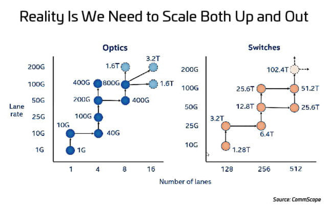
To deliver the additional bandwidth that data centers need, network designers have two options: scale up network speeds or scale up the number of paths (lanes) used to deliver data. Figure 1 illustrates the options for scaling up speeds (optics) and scaling out the number of lanes (switches).
As network speeds increase, scaling up speed becomes difficult and expensive, from a cost and power perspective, and can be slow to implement. There are other trade-offs, as well. So, where should you focus your resources? It’s a tricky question because, to support 400G and 800G applications, data centers must scale up and out. There are a few important developments occurring that may make this easier.
Since 2019, the IEEE 802.3 task force has been working on the IEEE P802.3ck standard for 100G lanes. Hopefully they finish the standard in 2022. Speculation about 200G-per-lane standards is that they will be ready by 2025.
図 2:Timeline for the IEEE P802.3ck as of 2020年8月
Many data center managers feel the timeline for IEEE P802.3ck would put the industry behind schedule. Therefore, other options are being considered. One option (deploying more lanes [scaling out]), has already been used to reach 400G. 800G comes with the 100G electrical standard, with early pre-standard products shipping in 2021. To reach 1.6T, data centers could scale up to 200G lanes or scale out to 16 lanes. We address the eventual migration to 1.6T toward the end.
A fundamental challenge in attempting to reach the next speed plateau is deciding whether to increase the amount of fiber or use multiplexing to increase the number of signal-carrying wavelengths per fiber. Again, it’s a tricky question.
Meeting the demands of 400G, 800G and higher throughput speeds will generally involve a combination of wavelength division multiplexing (WDM) deployed over a more fiber-dense network. Adding wavelengths is easier than adding fibers. If you find yourself with too few fibers, however, you may be forced to pay more for WDM technology where cheaper parallel solutions would be a better choice. Considering the current technology roadmap, 16-fiber infrastructures are becoming more popular.
The trade-off (physical fiber versus virtual wavelength) is based on the application, with the major influencer being the transition costs. Capital and operating costs are compared to the cost of implementing the required physical fiber infrastructure. Since electrical speeds are slow and difficult to increase, it seems likely that more lanes/fibers/wavelengths will be needed.
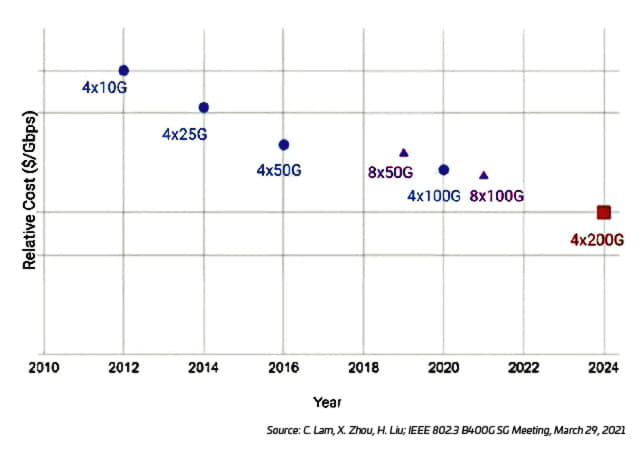
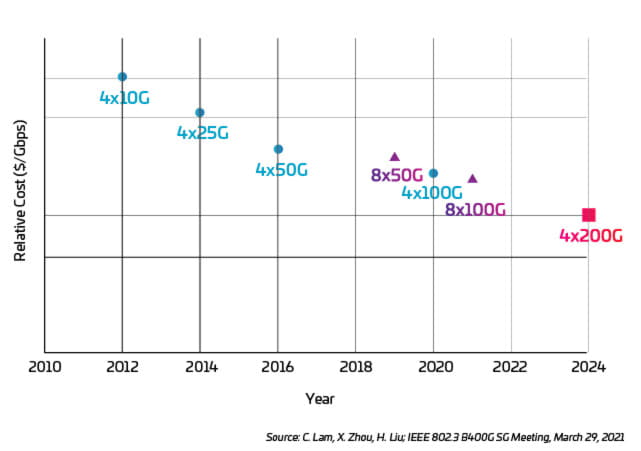
It is interesting to note that, while migrating to faster lane speeds has some specific cost-related issues, the relative cost of going faster might actually decrease, as illustrated in Figure 3.
図 3:Cost per Gbps versus optical lane speed
WDM is a common data center approach that uses different wavelengths of light to create multiple data paths on the same fiber. The two popular singlemode WDM technologies are coarse wavelength division multiplexing (CWDM) and dense wavelength division multiplexing (DWDM). CWDM is optimized for fewer channels and shorter reach applications, making it a lower cost WDM option. DWDM is optimized to achieve as much capacity on a single fiber as possible—making it expensive and useful primarily in long-haul networks.
Examples of Ethernet CWDM technologies include CLR4, CWDM4 and FR4. As the “4” would suggest, these technologies use four wavelengths, each carrying a data channel (1270 nm, 1290 nm, 1310 m and 1330 nm). This gives data center operators the ability to support higher throughput over duplex fiber-optic connections.
WDM options can provide more wavelengths (FR8, for example, uses eight wavelengths). The added capabilities require higher-priced optic modules, but longer distance applications could justify the cost increase.
There are two primary areas where WDM is expected to play a larger role in addressing the capacity crunch. The first is in the interconnects coming into the data center. Current and emerging applications like 5G, IoT and machine-to-machine (M2M) learning are driving the need for more high-speed connectivity between the data center and outside networks. WDM is being used to enlarge the capacity per fiber and meet the increased demand for capacity and speed while using existing fiber assets.
The second area where WDM is expected to have a more prominent role is in boosting connectivity between network switches. As data centers move from the traditional three-tier topology to mesh-type leaf-and-spine designs, server-port density becomes crucial. High-speed fiber switch connections support more server traffic while saving more ports for server connections. WDM increases the capacity of the existing duplex fiber networks without adding more fiber infrastructure—potentially saving time and money; greenfield installations may find parallel fiber options to be even more cost effective.
Multimode fiber also supports a third WDM-based technology: short wavelength division multiplexing (SWDM), which takes advantage of short (850 nm, 880 nm, 910 nm and 940 nm) wavelengths spaced 30 nm apart. In the data center, SWDM is especially attractive because of its capacity and cost-effectiveness in short-reach applications. SWDM running on MMF provides twice the speed of a WDM over a bi-directional (BiDi) duplex transmission path.
This enhanced capability provides data center managers an attractive upgrade path for their duplex architectures and enables faster speeds over extended distances. Using parallel fibers, multimode now reaches 100 m at 400G; with IEEE 802.3ck and 802.3db nearing completion, that speed is set to increase to 800G. This path is optimized with OM5 wideband MMF (WBMMF) cabling, which provides superior support for WDM on multimode.
For more information on this capability, check out our article about OM5 fiber.
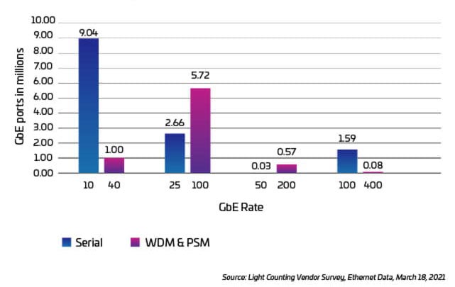
図 4:Annual port shipments of Ethernet SMF optics, 2020
図 5:WBMMF simultaneously transmits four wavelengths
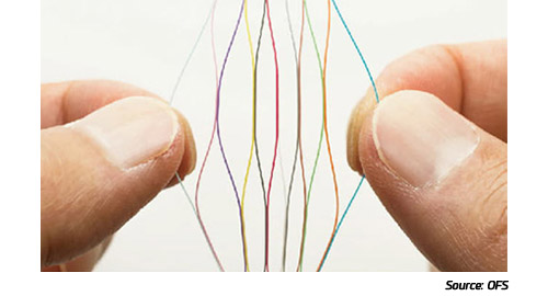
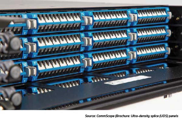
Historically, the core network cabling contained 24, 72, 144 or 288 fibers. At these levels, data centers could manageably run discrete fibers between the backbone and switches or servers, then use cable assemblies to break them out for efficient installation. Today, fiber cables are deployed with as many as 20 times more fiber strands—up to 6,912 fibers per cable. The increase is driven, in large part, by the switch to more fiber-dense mesh fabric networks. The any-to-any connectivity between servers and switches is also pushing the development of high- and ultra-high-density patch panels, which—in turn—require smaller form factor connectors and modules.
So where is the higher fiber-count cabling being deployed? One area is the data center interconnects (DCIs) where outside plant cables (whose fiber counts are also increasing) enter the data center. DCI trunk cabling with 3,000+ fibers is common for connecting two hyperscale facilities, and operators are planning to double that design capacity in the near future.
Higher-count fibers are also being used where backbone trunk cables—between the core switches and meet-me rooms—connect to cabinet-row spine switches. The increasing fiber counts are necessary but they create two big challenges. The first is, how to deploy it in the fastest, most efficient way? This involves physically putting it on the spool, taking it off and running it between points and through pathways. Once it’s installed, the second challenge is breaking it out and managing it at the switches and server racks. 詳細:データセンターでの高いファイバー芯数に適応.
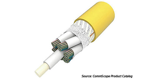
図 6:Example of high fiber-count cabling
図 7:Rollable ribbon fiber
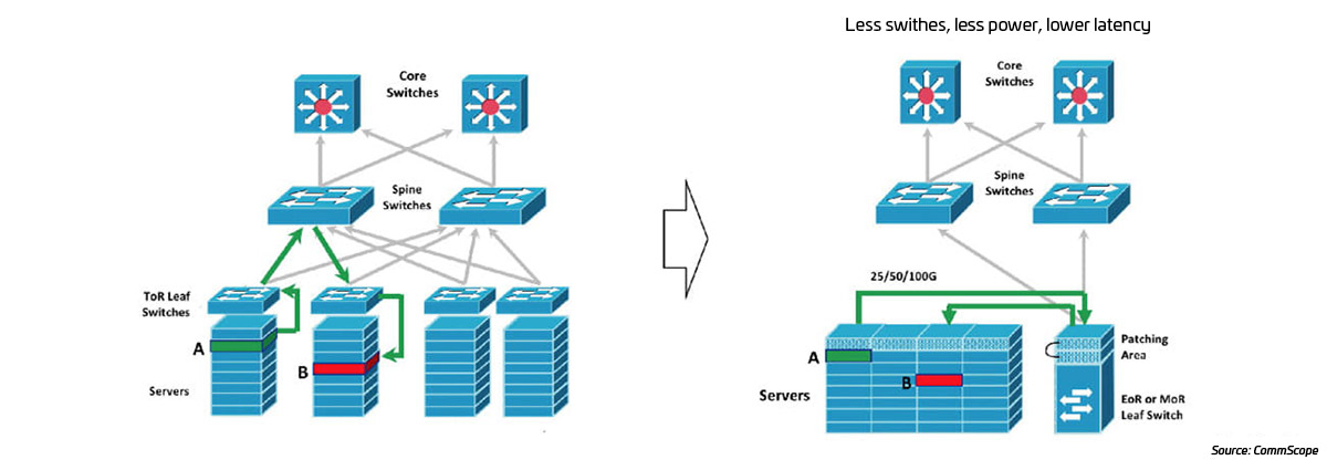
The current trend among data centers and larger enterprise networks is toward a fiber-dense mesh architecture that optimizes east-west traffic (often 10X north-south traffic)—still a spine-leaf orientation but with fewer network layers and often with a view to higher server attachment speeds. The highest volume of connections is at the edge where servers are connected. Servers represent overhead; therefore, the fewer switches (and the lower their latency), the better.
Most spine-leaf networks today have several layers or tiers. The size of the data center (number of servers to be connected) determines the number of network switching tiers and which also determines the maximum number of leaf switches that connect to the switches. Often the lowest tier is situated at the top of server racks (ToR). This design was optimal for legacy smaller (low-radix) switches providing fewer lower-speed server attachments. A ToR switch would roughly match up with the number of servers in a rack. With all of the links within a rack, short, low-cost connections between the server and the ToR switch often use low-cost copper connecting cables (DACs).
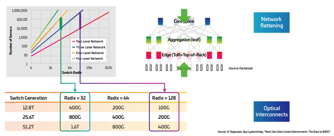
Moving to higher radix switches means—even though you’re still using the same 32-port switch—there are twice as many lanes (eight per switch port) available to attach servers. This provides an intriguing opportunity. With the higher radix switches, you can now migrate to a design in which multiple ToR leaf switches are replaced by a single tier-1 leaf switch. This single switch can now support about four cabinets of servers. Structured cabling connects the reduced number of server leaf switches, either end-of-row (EoR) or middle-of-row (MoR). Eliminating the ToR switches means fewer hops, lower application latency and a cheaper, more efficient design.
図 8:Higher radix switches enable more efficient EoR/MoR designs
The ideal solution for this application will require that the radix be maintained with eight connections per optic module. Maintaining lower costs for this option is enabled by using less costly MM optics, as well as new 400GSR8 application support for eight 50 Gb server connections over 100 m of OM4 cabling. Looking ahead, development in the 802.3db standard is targeting doubling the lane speed to 100 Gb over this same MMF infrastructure1. This is ideal for higher density AI/ML pods, which absolutely require much higher server network speeds but do not need longer network links that would require higher cost SM optics.
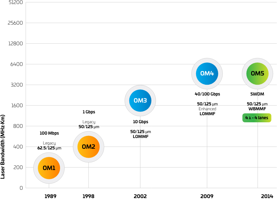
When OM4 was launched in 2009, OM3 was the market-preferred fiber type, yet few were willing to embrace the new OM4 technology. It wasn’t until advancements in Ethernet technology reduced the reach of OM3 to 70 meters that OM4 adoption took off. Today, OM4 is the preferred fiber type, but Ethernet technology is evolving once again—giving rise to OM5.
OM5 fiber offers two main advantages over OM3 and OM4. First, its attenuation (3 dB/km) is lower than that of OM3 and OM4 (3.5 dB/km). Secondly, the effective modal bandwidth (EMB) specification for OM3 and OM4 is limited to 850 nm, whereas the EMB for OM5 extends from 850 nm to 953 nm. The extended EMB window makes OM5 ideal for SWDM, which transmits several data streams on multiple wavelengths over a single fiber. This capability also makes OM5 a key enabler of 400GBase-SR4.2—and an important piece of a 400G migration strategy, since it enables extended reaches of up to 150 m.
For a deeper dive into OM5 and the optics being used to leverage its benefits, check out the MMF chapter in The Enterprise Source.
図 9:Evolution of MMF classes
参考資料:MMF, Fact File, CommScope, 2021
Singlemode and multimode infrastructure complement different applications in the data center. Finding the right mix of applications optimizes your cost for the optical links. Getting it right, however, is tough, as the cost and capabilities of each media are advancing. Let’s explore the elements to consider when making this decision.
Link distances
Data centers generally require a large number of network links with relatively short distances. By “short,” we generally mean less than 100 m. By contrast, medium reach is usually defined as 500 m for most large-scale data centers. Long-reach distances, such as those found in a campus or very large-scale data center, are typically 2 km or more.
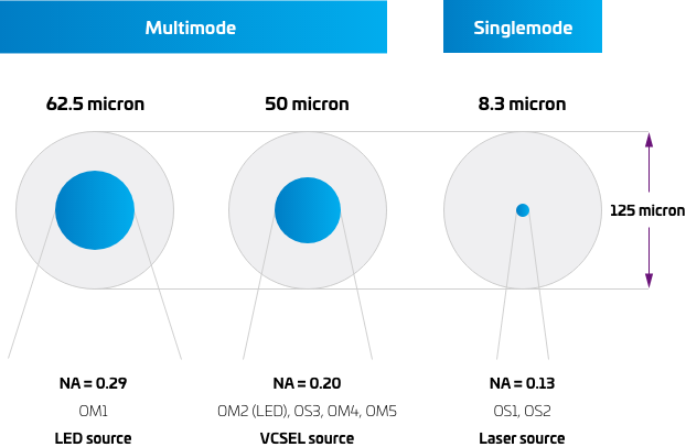
Singlemode, with its long-distance capabilities and promise of “unlimited” bandwidth, is commonly used in hyperscale data centers. More specifically, it is used at the entrance facilities to terminate DCI links from metro/wide area networks. In fact, many long-reach, high-speed options are only available in singlemode.
図 10:Anatomy of multimode and SMF
参考資料:MMF, Fact File, CommScope, 2021
Volume of links
Any discussion of link volumes in the data center must start with the ubiquitous servers—the most numerous elements in the network. In today’s configurations, servers are now being attached at 100G and higher. The fiber use case for these attachments involves lower cost multimode VCSEL-based optics, which must be implemented at both ends of the link. Given the sheer number of servers in even a moderately sized data center, the combined number of optic ports required makes this application very cost sensitive.
As you move to higher network tiers, however, the number of fibers decreases quickly based on the radix of the switches and other architectural considerations. Additionally, the distances often exceed the 100 m short reach limit imposed on multimode—making singlemode technology the only viable choice.
The good news is that the price of pluggable singlemode optics continues to drop. As a result, we’re seeing 100G Ethernet capturing a larger share of the data center switch port market. But the conversation regarding transmission types must go well beyond the cost of pluggable optics. It must also include an analysis of total channel cost, as well as the anticipated growth of the data center and its migration roadmap. Consider the following issues before making any decision.
Network topology: Some data centers may have more than 100,000 servers while others may have just a few. Some use a centralized placement of network equipment while others distribute networking equipment throughout the data center. These design requirements and choices determine the number of network links and the distance the network links must support.
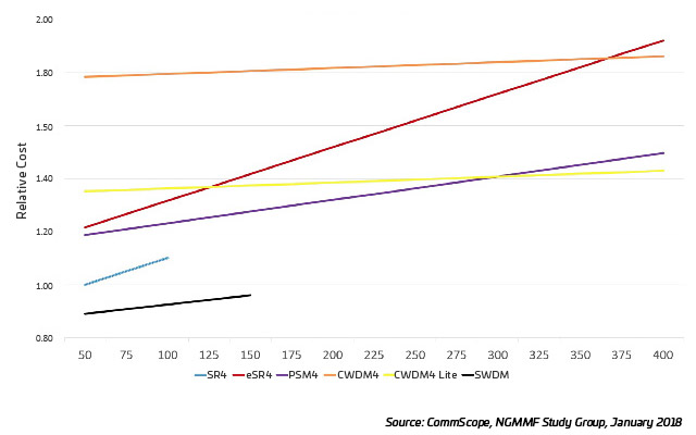
Total channel cost: Comparing link costs between fiber types involves assessing the cost of the entire link—transceivers, trunks and patch cords. A variety of costing models have been developed to help compare the relative cost of different network link types. For example, when choosing between 100G CWDM4 and 100G PSM4, a longer average link length tends to favor the duplex option. However, a brownfield installation may not have enough fiber available to support PSM4 links.
Other considerations: Differences in installation and maintenance can favor use of MMF. Some key considerations include:
- Sensitivity to dust/dirt: A larger fiber core is less sensitive to contamination. This is important in high-volume server connectivity.
- Link speeds: MMF currently operates at a maximum speed of 100G per wavelength.
- Infrastructure life cycle and stability—how quickly does the data center need to ramp up capacity?
図 11:100G link cost relative to SR4, 2X TRx trunk, 2X 3 m cords
Data center capacity is built on the physical fiber-optic cabling, which must constantly adapt to new optics to increase the speed and efficiency of data transmission by preserving as much of the data signals as possible. Fiber cabling and connections lose a certain amount of signal (laws of physics), but their performance has kept on improving. Today, ultra-low-loss (ULL) components are designed to exceed the industry standard limits—providing support for advancing optic applications using preterminated cabling systems. But what does “ultra-low-loss” mean?
It’s a common claim that preterminated systems have ultra-low-loss performance. But, with no ULL standard, how can performance be compared? In other words, if you pay for ULL performance, how do you know you’re getting your money’s worth?
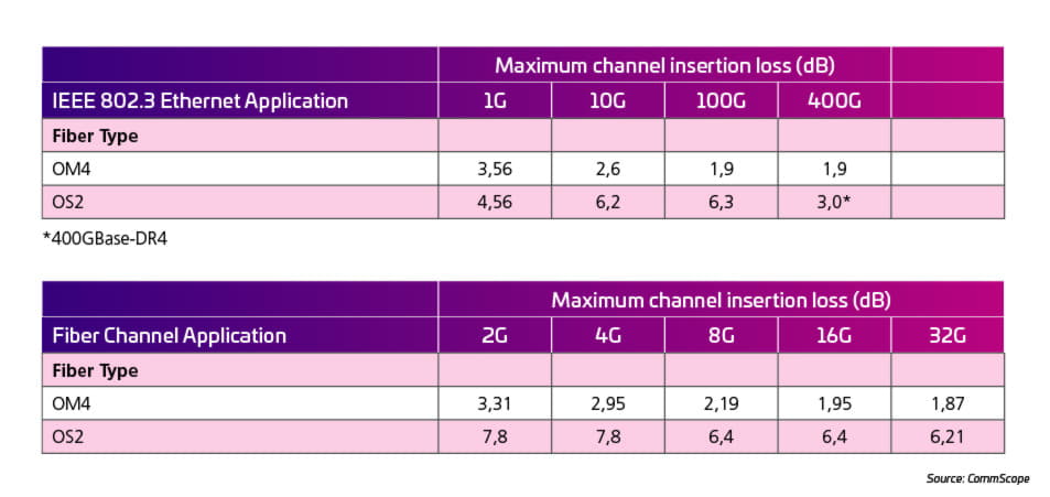
In years past, the bandwidth evolution of Ethernet and Fiber Channel applications led to a tremendous reduction of channel loss budgets and channel length. Table 1 shows that the insertion loss (IL) requirements for the cabling channels are getting more stringent for both multimode and singlemode channels. Traditionally, the optical performance parameters of preterminated MPO trunks and MPO/LC cassettes are expressed in terms of the cassettes’ insertion loss (IL) and return loss (RL) in dB (including the trunk connector). Currently, the best performing systems in the market claim a 0,35 dB IL performance.
表 1:Insertion loss requirements for multimode and singlemode channels
These performance figures are based on the configuration shown in Figure 12 designed for a 100GBase-SR4 application using cable attenuation specified by international standards.
図 12:Standard attenuation for a channel configuration for a 100GBase-SR4 application
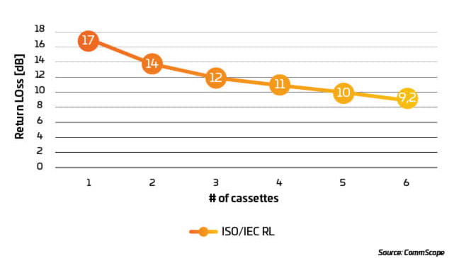
The above example is based on a four-cassette configuration, but what if the channel requires more than four cassettes? As a rule, the more connectors in the channel, the lower the channel’s return loss. For the above case, the RL needs to be above 12 dB for the optical transceiver to function properly. Based on the RL per connection as stated in ISO/IEC 11801-1 ed.3, each connection must have a minimum RL of 20 dB. Every cassette in a preterminated system has two connections (rear and front). Using the channel configuration in Figure 12 and the RL requirement in ISO/IEC 11801-1 ed.3, the channel’s RL will drop below the 20 dB RL threshold after the third cassette. This can be seen in Figure 13.
These observations show that optical performance considerations must include both IL and RL to ensure the function of the application. SYSTIMAX® ULL solutions from CommScope go much further.
- Maximum design flexibility through six-cassette channels
- Extended channel length for less than six cassettes
- Tool for design and testing support
- アプリケーション保証
図 13:Total RL of X number of cassettes
SYSTIMAX ULL solutions combine outstanding optical performance with statistical approaches that ensure true ultra-low-loss performance for both Il and RL.
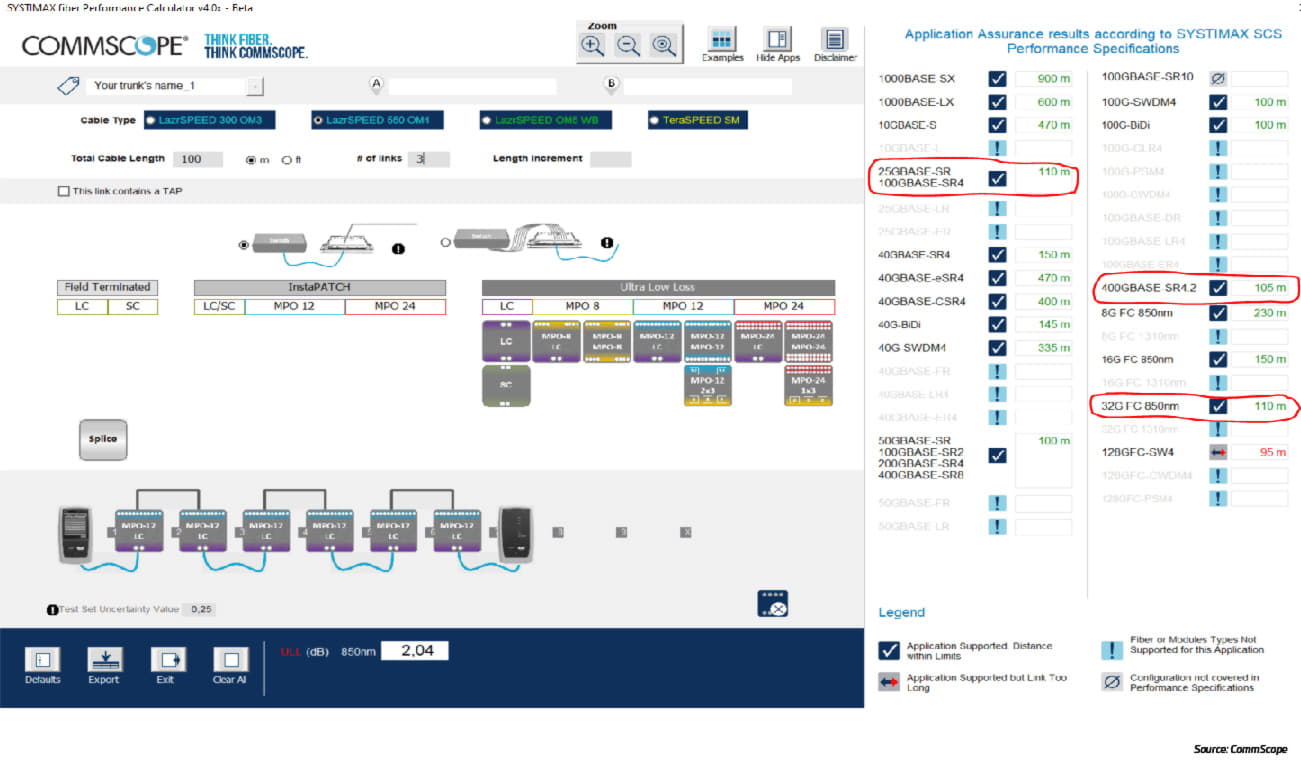
CommScope’s Fiber Performance Calculator can be used to design cabling channels and verify the function of applications, including their maximum link length.
The configuration below indicates that, even with six cassettes in a row, the channel length exceeds standard application lengths (see marked applications).
CommScope stands behind the performance of our products, with warranty assurance for many supported optical applications. The SYSTIMAX Fiber Performance Calculator design tool and application support guidelines are specific to the SYSTIMAX Application Assurance.
Under the terms of CommScope’s 25-Year Extended Product and Application Warranty (“System Warranty”), the SYSTIMAX System Specification contains an Application Assurance that guarantees designated cabling and optical applications will meet performance specifications as set forth therein, in accordance with the SYSTIMAX Performance Specifications.
The System Warranty and SYSTIMAX Specifications provide details of the terms and conditions of our System Warranty and SYSTIMAX Application Assurance. The current published 25-Year Extended Product and Application Warranty is available here.
The current SYSTIMAX System Specification and Application Assurance may be found at SYSTIMAX Application Assurance.
その他のリソース
The current trend to regional data center clusters is driving the need for higher capacity, lower cost DCI links. New IEEE standards (see the standards section below) will pave the way for lower-cost plug-and-play options with point-to-point deployments, but data center operators have difficult decisions to make regarding coherent versus direct detection, modulation schemes and how to manage growing fiber counts.
Look for more information on this subject in an upcoming article.
Combining the four pillars to enable 400G/800G and above
The four pillars of the data center infrastructure—port density, transceivers, connectors and cabling—provide a logical way to view the core components needed to support 400G and beyond. Within each pillar are a multitude of options. The challenge for network operators is understanding the pros and cons of the individual options while, at the same time, being able to recognize the inter-relationship between the four pillars. A change in cabling will most likely affect the proper selection of transceivers, port configurations and connectors. Those designing and managing the networks of the future must simultaneously live in the micro and the macro. The following are examples of where this is being done.
In greenfield projects, network and facility designers have the luxury (and challenge) of creating higher speed infrastructures that can hit the ground with 400G, 800G or even 1.6T from day 1. So, what exactly does that require? Below are some trends and insights to consider when designing a higher speed infrastructure from the ground up.
Port densities: For leaf-spine switch applications, the market favors the highest radix (number of ports) per switch. To achieve the most efficient design, networks minimize the number of switch fabric tiers (flatten). Newer ASICs support more I/Os but, as speeds increase, there is a trade-off between lane rate and radix. Radix, however, is the key in reducing the number of switches for a given size of network. As seen in Figure 14, a typical hyperscale data center contains about 100,000 servers; a network of this size can be supported with just two tiers of network switches. This is due, in part, to fast-evolving ASICs and modules, which enable higher radix switches and higher capacity networks.
図 14:Higher radix can help reduce the number of switches
Transceiver technologies: As discussed in Part I, the two dominant form factors for 400G are QSFP-DD and OSFP. Both will support up to 32 ports in a one-rack-unit (1RU) switch and accept LC, MPO, SN (OSPF) and CS connectors. The key differences are that the QSFP-DD is backwards-compatible with QSFP+ and QSFP28, whereas the OSFP requires an adapter for backwards compatibility. The OSFP transceivers, which are designed for 800G as well, may also have more shelf life. Each ASIC I/O must be mapped through the transceiver to an individual optical port to maintain the switch radix. Cabling infrastructure must also map these optical ports to server links.
Cabling and architecture: Cable pathways need to account for very high fiber-count cables, especially in the backbone network and data center interconnects. Taking advantage of new cabling designs with reduced footprints—like 200-micron and rollable ribbon fiber—will help minimize cable routing and bend radius issues. Regardless of size, greenfield data centers need to prepare for cloud architectures. This involves an optimized direct path for server-to-server communication using a “leaf-spine” architecture. This design allows applications on any compute and storage device to work together in a predictable, scalable way, regardless of their physical location within the data center. The fabric has inherent redundancy, as multiple switching resources are spread across the data center to help ensure better application availability. The total fabric bandwidth can be calculated by multiplying the number of edge ports by the speed of the edge ports—or the number of spine ports by the speed of the spine ports. If there is no oversubscription, these two numbers will be the same.
Many existing installations were designed as low loss or ultra-low loss using eight-, 12-, or 24-fiber subunit MPO trunks. 400G and 800G applications, however, are optimized using 16 fibers to the transceiver. While 16-fiber-based designs simplify migration and breakouts for greenfield applications, existing installations built with eight-, 12- or 24-fiber subunit trunks may still support the faster octal applications.
Some things to consider when deciding which configuration makes the most sense are: channel loss performance, fiber counts between endpoints, fiber type (SM, OM4, OM5), polarity, MPO trunk cable lengths and gender.
Channel performance, including IL and RL, should be tested and documented using handheld test equipment to meet SM and MM application requirements. A CommScope application like the SYSTIMAX Fiber Performance Calculator may be run to verify channel performance as a starting point.
Twelve-fiber subunit trunk cables have been available since the 1990s. At the time, they were effective for duplex applications. As the industry moved from duplex to multi-pair applications with MPO connectors, eight-, 24- and (most recently) 16-fiber subunits have been added. These are welcome additions, as support for the new octal applications requires sufficient fiber counts between endpoints. In some cases, data centers can leverage their existing cabling to meet the new demands, assuming the aggregate fiber count in the channel between locations enables the transition. If the fiber count between locations aligns with 16- or eight-fiber groupings, transition to the network ports may be done using breakout array cables.
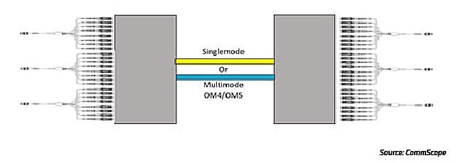
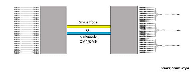
As an example, a verified channel consisting of 144 fibers in a trunk cable between panels with LC duplex ports as the front interface can terminate to a transceiver using an array cable of eight duplex LC connectors to MPO16 (Figure 15). The 144-fiber channel can support up to nine of these array cables in one RU. Additional array options, managing those fiber channels, can enable connectivity as well. Similarly, the 16-fiber ports can break out to duplex server ports on the far end.
図 15:16-fiber switch ports connected through traditional channel
As an example, Figure 16 shows a verified channel consisting of 144 fibers in a trunk cable between panels with LC duplex ports as the front interface.
図 16:16-fiber switch ports broken out to duplex server ports
There are also 400G and 800G applications splitting eight lanes of 50G or 100G into 2 x 4 lane applications for 200G or 400G deployments. For these applications the connections for legacy MPO8 trunks can utilize MPO16 to 2x MPO8 array assemblies as seen in Figure 17.
図 17:2x MPO8-to-MPO16 array
Another way to enable conversion assemblies to fully utilize existing fiber is by terminating the trunk cables to inline adapter packs. This is efficient for utilizing existing fibers but can present cable management challenges. If not implemented correctly, breakout lengths and port locations can strand capacity. Ensure ports are localized and located within a rack or cabinet to enable full utilization.
Caution about pinned and non-pinned connections: Because an MPO-based transceiver has internal alignment pins, its connecting equipment or patch cable must be non-pinned on the equipment side. If using MPO conversion cables, use an adapter to connect the opposite end of the cable to the trunk cable. If the trunk cable connections are pinned as well, the conversion cables must be non-pinned to non-pinned. If the trunk cables are non-pinned, the mating end of the equipment cable must be pinned. Technicians will need to ensure the proper end is connected to each side to avoid possible optics damage from a pinned cord.
A word about polarity: While the industry has been shifting to Method B polarity for its simplicity in duplex and multi-fiber connectivity, other legacy polarity schemes are still deployed in data centers. If the performance and fiber counts of the installed channel meet the application needs, customized transition cables may be used to connect to high-speed transceivers.
その他のリソース
802.3bs
The IEEE introduced several new standards enabling 400G applications. An important decision was made to introduce a new modulation scheme, PAM4. PAM4 enables electrical and optical lanes to progress to higher speeds than were practical with traditional NRZ modulation. PAM4 effectively doubles the lane rates—25G to 50G—as well as the number of lanes—four to eight. As a result, 400G optical transceivers are now standardized.
802.3cm
This standard, which addresses 400G over MMF, introduced support for four-pair (400GBASE-SR4.2) and eight-pair (400GBASE-SR8). Both applications use VCSELs, which continue to provide higher bandwidth while maintaining lower cost and power designs compared to SMF alternatives. SR4.2 and SR8 also both use the 100 m short-reach MMF transceivers designed for high-volume, high-speed server links. This is notable because, as speeds increase, copper cables must become shorter. At the same time, higher radix capabilities help collapse network layers by eliminating TOR switches. A low-cost MMF optic-to-server connection supports this design and saves money.
802.3ck (draft)
With the introduction of PAM4, a next step for supporting higher speeds is increasing the lane rate of the electrical and optical signals to 100G. This is the focus of the pending 802.3ck standard. When completed, this standard will have a positive impact on the cost per bit for 400G applications and will enable 800G modules (the 800G MAC rate is being proposed via the IEEE Beyond 400G study group). This standard is nearing completion and should be complete in 2022.
802.3cu
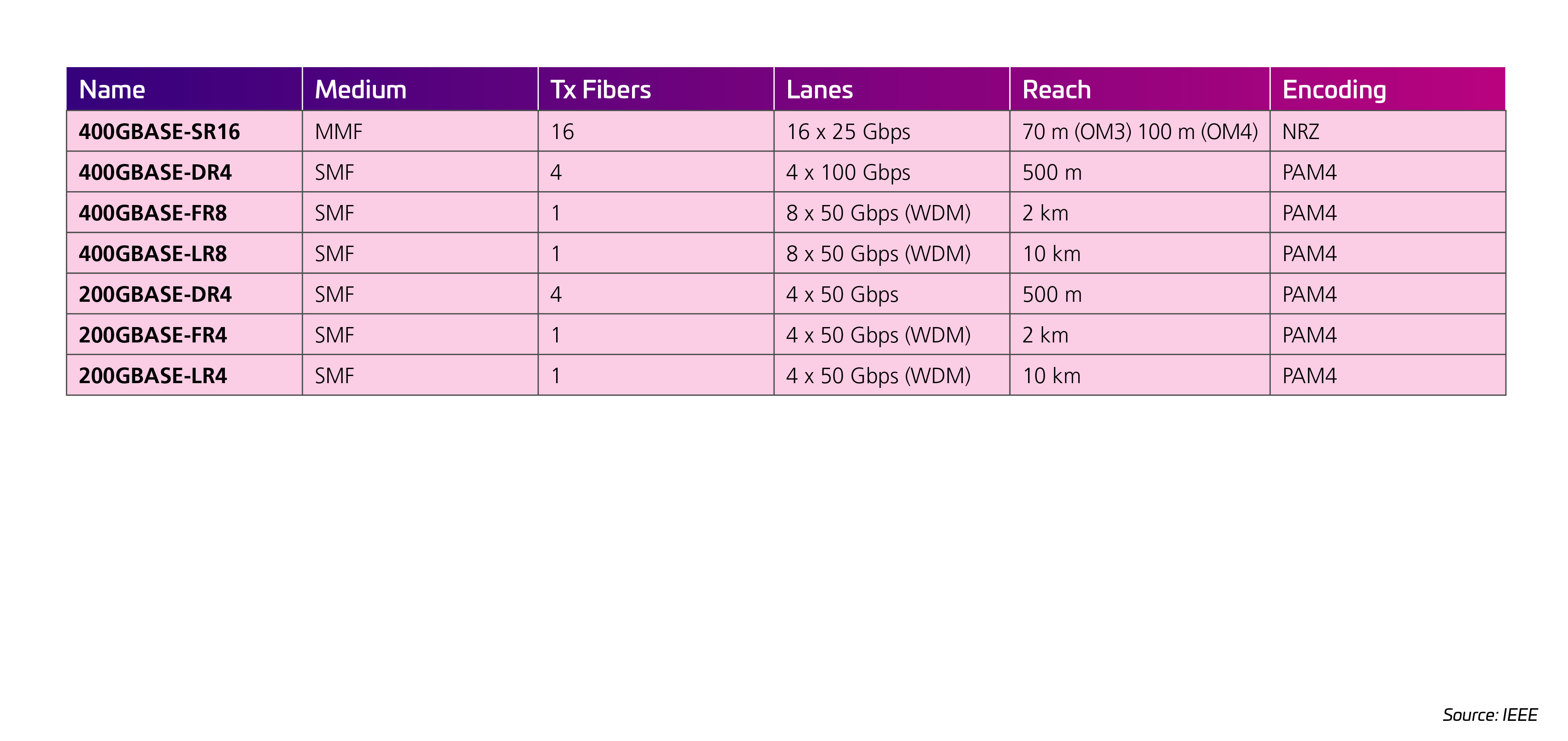
802.3cu は 100G および 400G モジュール(現在は 100G レーンに基づく)を導入し、DR、FR、LR、ER オプションを追加しす。Nomenclature options now include the lane count; 400GBASE-FR4 defines four lanes of 100G over four wavelengths using two fibers with a 2 km reach (the F). The task force could not agree on a 10 km reach (for the LR4) and agreed on a 6 km maximum distance. Therefore, a new nomenclature (400GBASE-LR4-6) was created in which “6” stands for 6 km—vs the common “L,” which signifies a 10 km reach.
Though the 802.3cu standard was completed prior to the 802.3ck standard, the long-term view sees 100G electrical lanes matching 100G optical lanes. This will reduce the need for gear-box rate matching, required for 25G and 50G standards. The common optical interface is expected to coalesce to 100G in the future—facilitating backwards compatibility across several ASIC generations.
802.3db (draft):
At the time of writing, the 802.3db task force continues to add MMF implementations that augment those in 802.3cm. These new implementations increase lane rates to 100G with a lane count of eight—setting the stage for 400G and 800G over 100 m of OM4. MMF server connections are a prime focus. Given the high volume of these connections, cost of the optics is important. As many servers to Tier 1 (leaf) links will likely be in-row and very short, 802.3db seeks to optimize applications of less than 50 m. The addition of “VR” to the nomenclature identifies the 50 m reach, while SR will continue to denote 100 m reach. Anticipated applications include 400GBASE-SR4 using eight fibers, with QSFP-DD optics remaining at eight lanes to match the ASIC I/O capacity. So, 16-fiber implementations will be used for 2X400G SR4. An 800G capacity is also available. But, since there is no IEEE 800G MAC at this time, this standard will not yet address 800GBASE-SR8.
Moving to 800G
Things are moving fast, and—spoiler alert—they have just jumped again. The good news is that, between the standards bodies and the industry, significant and promising developments are underway that will get data centers to 400G and 800G in the near future. Clearing the technological hurdles is only half the challenge, however. The other is timing. With refresh cycles running every two to three years and new technologies coming online at an accelerating rate, it becomes more difficult for operators to time their transitions properly—and more expensive if they fail to get it right. Here are some things to keep in mind as you plan for the changes to come.
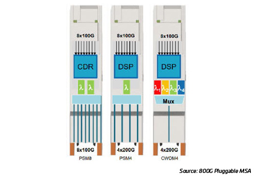
With 100G I/Os doubling switch port speeds, the same 400G cabling strategies and higher bandwidth MMF can support the transition to 800G modules. The 800G Pluggable MSA is capitalizing on the introduction of octal modules and 100G electrical lanes to develop implementation agreements for 800G optic applications. Engineers are moving quickly to add support for breakout options such as 2x400, 4x200 and 8x100; still, applications requiring an 800G MAC are limited at this time.
The IEEE has launched a study group to help transition to the next plateau of higher Ethernet rates. 800G is certainly on the map, and a path to 1.6T and beyond is also being explored. As work begins, many new objectives are introduced. There is broad industry participation in this study group, including the largest network operators who view standards as necessary to the network ecosystem.
It’s very possible that these standards will be used to develop new module strategies to reach 1.6T. The Optical Internetworking Forum (OIF) is now working on a 3.2T Optic Engine—a miniaturized version of a transceiver that is optimized to sit “co-packaged” beside the switching ASIC.
The industry’s multi-source agreement (MSA) consortiums are involved in ongoing efforts to accelerate the development and adoption of new or novel network technologies. In some cases, such as adding 800G implementations, MSA efforts may result in new technologies being developed before the completion of the industry standards.
800G Pluggable MSA
In 2019年9月, an 800G pluggable MSA was formed. IEEE work on 100G VCSELs is still ongoing, so the MSA opted to work on a low-cost singlemode replacement for the popular 8x100G SR MMF options. The goal is to deliver an early-market, low-cost 800G SR8 solution that would enable data centers to support low-cost server applications. The 800G pluggable would support increasing switch radixes and decreasing per-rack server counts
図 18:8x100, 2x400 GbE modules
400G BiDi MSA
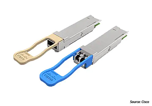
In 2018年7月, the 400G BiDi MSA was formed to promote adoption of interoperable 400G optical transceivers for 100 m bi-directional transport over MMF. In 2019年9月, the MSA announced the publication of release 1.0 of its 400G-BD4.2 specification for a 400G optical interface over 100 m of MMF. The specification leverages 100G BiDi for Ethernet applications and is compatible with the widely deployed parallel MMF cabling infrastructure. 400G-BD4.2 addresses short-reach applications, including the critical high-volume reaches in modern data centers between switches. While these are important steps forward, they do not advance the technology beyond the IEEE 802.3cm standard.
図 19:400G MMF Bi-Di and SMF
100G Lambda MSA
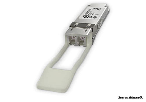
In 2020年10月, the 100G Lambda MSA Group announced its 400 Gigabit Ethernet specification that supports PAM4-enabled, 100G-per-wavelength transmission up to 10 km. The 400G-LR4-10 standard is for duplex singlemode links up to 10 km. It relies on multiplexing four wavelengths of 100G PAM4-modulated optical signals. Among other things, it ensures multivendor interoperability for optical transceivers in various form factors. Currently, the 100G Lambda MSA Group is addressing extended-reach specifications beyond 10 km.
図 20:Single lambda PAM4 QSFP
OSFP MSA
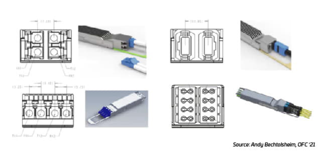
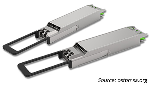
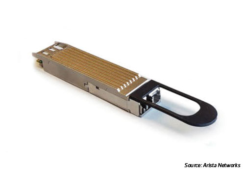
The OSFP MSA was created in 2016年11月 to focus on defining a next-generation, forward-compatible pluggable module form factor for high-speed networking applications. In 2021年5月, the group released the OSFP 4.0 Specification for 800G OSFP modules. While the OSFP module was designed from the beginning to support 800G, the OSFP 4.0 specification adds support for dual 400G and octal 100G breakout modules with dual LC, dual Mini-LC, dual MPO and octal SN/MDC fiber connector options.
図 21:OSFP-LS module
QSFP-DD MSA
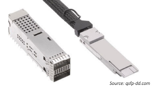
In 2021年5月, the QSFP-DD MSA group released revision 6.0 of its QSFP-DD/QSFP-DD800/QSFP112 hardware specification. The revisions update QSFP-DD and introduce QSFP-DD800 and QSFP112. Other changes include support for 100G electrical host interfaces and the addition of QSFP-DD800 and QSFP112 mechanical and board definitions. It also adds QSFP112 electrical and management timing and supports a higher module power rating of 25 watts.
図 22:QSFP-DD transceiver
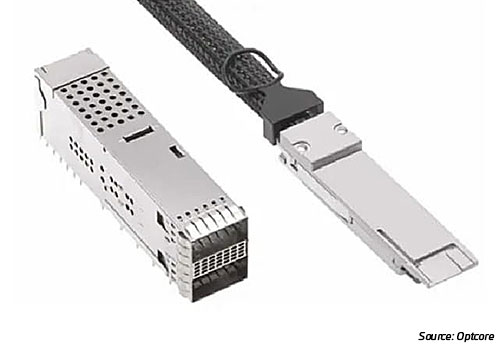
Beyond 800G (1.6T)
With the paint still wet on 400G and 800G modules, the race to 1.6T and 3.2T has already begun. There are technical challenges to solve and standards and alliances to build before we get there. Optical design engineers continue to weigh the cost and risk of increasing lane rates vs adding more lanes. Regardless, the industry will need all its tools to reach the next network speeds.
Many of the large data center operators see a pressing need to increase network efficiency while setting implementation timelines that are extremely challenging. The issue of power continues to hang over the industry and impact every decision. Energy consumption is a heavy tax that networks impose on data center applications, and it will become heavier as we consider future network speeds. Increasing link capacity is an important tool used to improve efficiency but, of course, the technology to do this needs to continually evolve. Figure 23 shows the cost and power improvements that are expected as speeds migrate higher.
図 23:Higher speed reduces the number of links required and reduces the power per bit for data center networks.
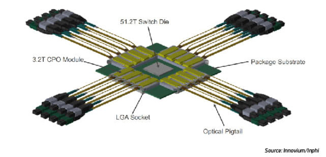
Co-packaged optics (CPO) represent a great opportunity to lower power requirements to a few pico-joules and set a path to 3.2T higher optic IO speeds. Getting there means solving some difficult technical challenges and re-imagining the networking supply chain and how it operates. If everything falls into place, we could see commercially available CPOs sometime in 2025; otherwise, that timeline could be pushed back.
図 24:QSFP-XD 16 lanes with 100G per lane
On the other hand, there is a path that would see pluggable modules evolve to meet these network speeds without the need for CPO. Andy Bechtolsheim’s presentation at OFC ’21 set the stage for a competition between CPO and pluggables with the introduction to a new OSFP-XD MSA. Building on the 800G OSFP module specification, the OSFP-XD MSA doubles the lane count from eight to 16. These lanes will operate at 100G and deliver a module capacity of 1.6T. The thinking is that the ASIC-to-module electrical challenge can be solved with known technology. The power estimation is ≈10 pJ, putting it within the target range for the 1.6T generation. The time to market comes sooner and with less risk when compared to CPO.
図 25:The OSFP MSA has introduced the next-generation specification “OSFP-XD” or extra density with 16 electrical I/Os and expected 200G/lane capability
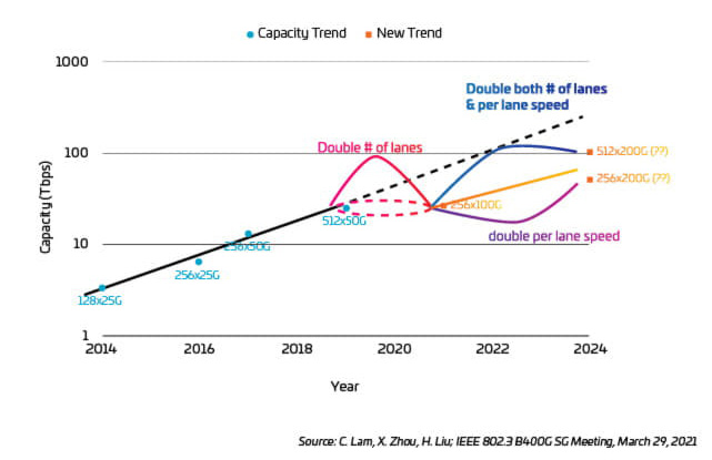
As shown in Figure 26, getting to 3.2T will most likely require 200G electrical/optical lanes (16 * 200G). If the lane rate does not increase, then the number of parallel fibers or wavelengths would need to double—and both of these options are not desirable (and perhaps not feasible).
Consider that increasing the electrical lane rates is difficult work. The IEEE802.3ck task force has been working on this 100G electrical standard since 2019年5月 and is currently expected to complete their work in late 2022. A new IEEE project will take on the next steps, including 200G electrical signaling. This work will likely be very challenging, and current estimates suggest this technology might be ready in 2025.
Regardless of the initial path—pluggable modules or CPO—200G electrical I/Os seem to be a necessary step. CPO advocates view their path to 200G as the natural next step, given the advantages of their architecture. Those who champion the module approach, however, believe they can scale the OSFP-XD to be compatible with 200G. In their view, the reduction in node numbers enables the overall objective to be met, as silicon advancements will reduce power requirements.
What we do know is that 200G I/O is critical if data centers are to successfully scale their switch bandwidth and the efficiency of their networking fabric. Moreover, faster optical lane speeds are key to lowering overall cost and improving power efficiency. Modules and CPOs both provide potential paths to 200G lanes. Either path is difficult and risky, but a way forward must be found.
At 200G optical lanes (even singlemode fiber) will see a reduction in reach capability to the point that current topologies based on 2 km reach may be at risk. Perhaps, as we approach these higher speeds, we will see other technologies become more attractive. One possibility is coherent pluggable modules, which are becoming more cost effective and power efficient. We may also see the introduction of more coherent modules in DC/DCI applications as speeds continue to increase.
図 26:Capacity Trends 2014-2024
Conclusions
Admittedly, there is a long list of things to consider regarding a high-speed migration to 400 Gb and beyond. The question is, what should you be doing? A great first step is to take stock of what you’ve got in your network today. How is it currently designed? For example, you’ve got patch panels and trunk cables between points, but what about the connections? Do your trunk cables have pins or not? Does the pin choice align with the transceivers you plan to use? Consider the transitions in the network. Are you using MPO-to-duplex, a single MPO to two MPOs? Without detailed information on the current state of your network, you won’t know what’s involved in adapting it for tomorrow’s applications.
Speaking of future applications, what does your organization’s technology roadmap look like? How much runway do you need to prepare your infrastructure to support the evolving speed and latency requirements? Do you have the right fiber counts and architecture?
These are all things you may already be considering, but who else is at the table? If you’re on the network team, you need to be in dialogue with your counterparts on the infrastructure side. They can help you understand what’s installed, and you can alert them to future requirements and plans that may be further down the road.
Finally, it’s never too early to bring in outside experts who can give you a fresh pair of eyes and a different perspective. While nobody knows your needs better than you, an independent expert is more likely to have a better handle on existing and emerging technologies, design trends and best practices.
エンタープライズ向けデータセンターソリューション
ソリューション
ハイパースケールおよびクラウド型データセンター
ソリューション
マルチテナント型データセンター
ソリューション
サービスプロバイダー向けデータセンター
見識
マルチモードファイバー:ファクト ファイル
リソース
高速移行ライブラリテスト 0
仕様情報
OSFP MSA
仕様情報
QSFP-DD MSA
仕様
QSFP-DD ハードウェア
見識
400G/800G への移行:ファクト ファイル - パート 1
一見すると、貴社のために競合するインフラストラクチャー・パートナーたちは、かなり多数出てきているようです。貴社にファイバーと接続を販売したいと考えているプロバイダーが数多くあります。しかし、貴社ネットワークを長期的に成功させるために何が重要かをよく見て考え始めると、その選択肢は狭まり始めます。ネットワークの進化を促進するには、ファイバーや接続性以上のものが必要だからです。これがコムスコープが必要とされる所以です。
パフォーマンスの向上:コムスコープの革新と性能の歴史は 40 年以上に及びます。当社のシングルモード TeraSPEED® ファイバーは最初の OS2 規格の 3 年前にデビューし、当社がパイオニアである広帯域マルチモードは、OM5 マルチモードを生み出しました。現在、当社のエンド・ツー・エンドのファイバーおよび銅ケーブルソリューションおよび AIM インテリジェンスは、お客様が必要な帯域幅、構成オプション、超低損失の性能により、最も要求の厳しい数々のアプリケーションをサポートし、自信を持って成長することができます。
機敏性と適応性: 当社のモジュール式ポートフォリオにより、ネットワーク内の需要の変化に迅速かつ簡単に対応できます。シングルモードおよびマルチモード、事前終端処理済みケーブル・アセンブリ、柔軟性の高いパッチパネル、モジュール式コンポーネント、8 芯、12 芯、16 芯、および 24 芯ファイバー MPO 接続、超小型フォームファクタのデュプレックスおよびパラレルの各種コネクタ。コムスコープは、あなたを高速でアジャイルに、そして日和見にします。
将来対応型 100G から 400G、そして 800G へと移行するにつれ、当社の高速移行プラットフォームは、より高いファイバー密度、高速レーン・レート、新しいトポロジーへの明確かつ優雅な道を提供します。ケーブルインフラストラクチャーを置き換えることなくネットワーク・ティアを縮小し、ニーズの変化に応じて高速で、低遅延のサーバー・ネットワークに移行します。1 つの堅牢で俊敏なプラットフォームが、あなたを今あるところから次なるところへと進化させます。
保証された信頼性:コムスコープは、アプリケーション保証により、お客様が現在設計しているリンクが今後何年にもわたってお客様のアプリケーション要件を満たすことを保証します。包括的なライフサイクル・サービス・プログラム(計画、設計、実装、運用)、フィールドアプリケーション・エンジニアたちのグローバルチーム、コムスコープの鉄のクラッドで覆われた 25 年保証により、この取り組みを支えています。
グローバルな可用性とローカルサポート:コムスコープのグローバルなフットプリントには、6 大陸にまたがった製造、流通、現地の技術サービスなどがあり、20,000 名の情熱的な専門家が参画しています。私たちは、いつでも、どこでも、必要なときに、お客様のためにお手伝いいたします。当社のグローバル・パートナー・ネットワークは、認定設計者、設置者、インテグレーターがネットワークを前進させ続けることを保証します。

