DHHTT65B-3XR
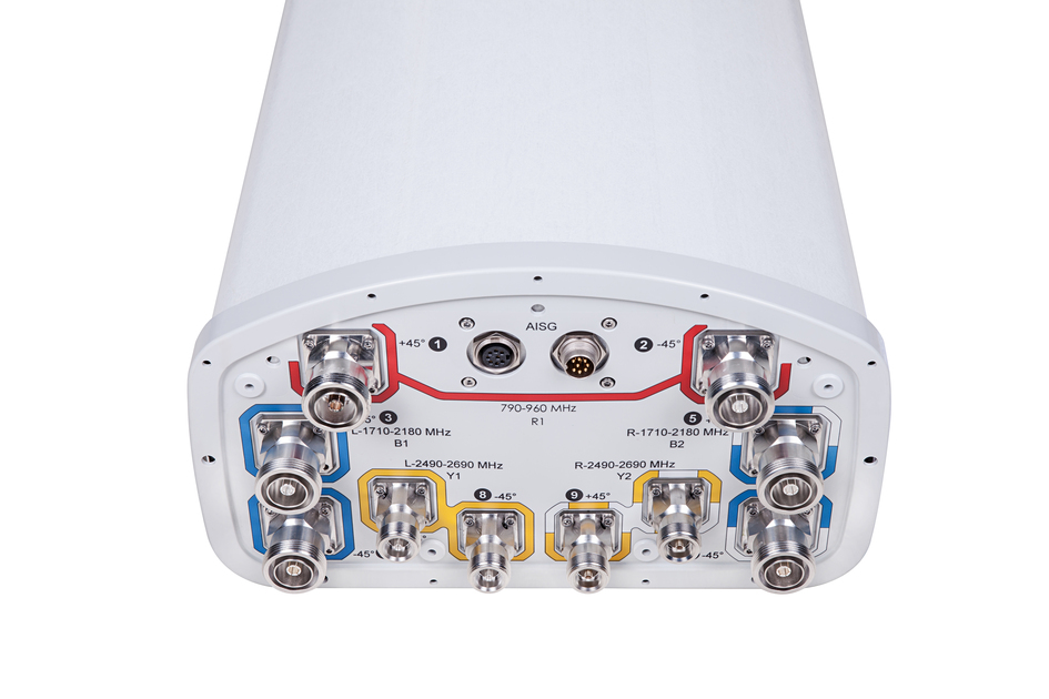
10-port sector antenna, 2x 790–960, 4x 1710–2180 and 4x 2490-2690 MHz, 65° HPBW, 3x RET with individual tilt available for the 850 MHz band, 1900 MHz bands and 2500 MHz bands.
Specifications
Specifications
General Specifications
| Antenna Type | Sector |
| Band | Multiband |
| Color | Light Gray (RAL 7035) |
| Grounding Type | RF connector inner conductor and body grounded to reflector and mounting bracket |
| Performance Note | Outdoor usage | Wind loading figures are validated by wind tunnel measurements described in white paper WP-112534-EN |
| Radome Material | ASA, UV stabilized |
| Radiator Material | Copper | Low loss circuit board |
| Reflector Material | Aluminum |
| RF Connector Interface | 4.1-9.5 DIN Female | 7-16 DIN Female |
| RF Connector Location | Bottom |
| RF Connector Quantity, high band | 8 |
| RF Connector Quantity, low band | 2 |
| RF Connector Quantity, total | 10 |
Remote Electrical Tilt (RET) Information
| RET Interface | 8-pin DIN Female | 8-pin DIN Male |
| RET Interface, quantity | 1 female | 1 male |
| Input Voltage | 10–30 Vdc |
| Power Consumption, idle state, maximum | 2 W |
| Power Consumption, normal conditions, maximum | 13 W |
| Protocol | 3GPP/AISG 2.0 (Multi-RET) |
Dimensions
| Width | 301 mm | 11.85 in |
| Depth | 181 mm | 7.126 in |
| Length | 1832 mm | 72.126 in |
| Net Weight, without mounting kit | 20.6 kg | 45.415 lb |
Array Layout
| Click on image to enlarge. |

Electrical Specifications
| Impedance | 50 ohm |
| Operating Frequency Band | 790 – 960 MHz | 1710 – 2180 MHz | 2490 – 2690 MHz |
| Polarization | ±45° |
Electrical Specifications
| Frequency Band, MHz | 790–896 | 870–960 | 1710–1880 | 1850–1990 | 1920–2180 | 2490–2690 |
| Connector Interface | 7-16 DIN Female | 7-16 DIN Female | 7-16 DIN Female | 7-16 DIN Female | 7-16 DIN Female | 4.1-9.5 DIN Female |
| Connector Location | Bottom | Bottom | Bottom | Bottom | Bottom | Bottom |
| Gain, dBi | 15.5 | 15.5 | 17.3 | 17.4 | 17.5 | 17.2 |
| Beamwidth, Horizontal, degrees | 64 | 63 | 71 | 69 | 66 | 60 |
| Beamwidth, Vertical, degrees | 11.2 | 10.3 | 5.6 | 5.4 | 5.1 | 4.3 |
| Beam Tilt, degrees | 0–10 | 0–10 | 0–8 | 0–8 | 0–8 | 0–8 |
| USLS (First Lobe), dB | 15 | 16 | 15 | 16 | 15 | 18 |
| Front-to-Back Ratio at 180°, dB | 28 | 31 | 31 | 29 | 25 | 26 |
| CPR at Boresight, dB | 20 | 19 | 20 | 20 | 18 | 16 |
| CPR at Sector, dB | 9 | 9 | 9 | 9 | 7 | 4 |
| Isolation, Cross Polarization, dB | 25 | 25 | 25 | 25 | 25 | 25 |
| Isolation, Inter-band, dB | 30 | 30 | 30 | 30 | 30 | 30 |
| VSWR | Return loss, dB | 1.5 | 14.0 | 1.5 | 14.0 | 1.5 | 14.0 | 1.5 | 14.0 | 1.5 | 14.0 | 1.5 | 14.0 |
| PIM, 3rd Order, 2 x 20 W, dBc | -153 | -153 | -153 | -153 | -153 | -150 |
| Input Power per Port, maximum, watts | 350 | 350 | 300 | 300 | 300 | 250 |
Electrical Specifications, BASTA
| Frequency Band, MHz | 790–896 | 870–960 | 1710–1880 | 1850–1990 | 1920–2180 | 2490–2690 |
| Gain by all Beam Tilts, average, dBi | 15.0 | 15.1 | 17.0 | 17.1 | 17.1 | 17.1 |
| Gain by all Beam Tilts Tolerance, dB | ±0.4 | ±0.3 | ±0.3 | ±0.3 | ±0.3 | ±0.6 |
| Gain by Beam Tilt, average, dBi | 0 ° | 15.0 5 ° | 15.1 10 ° | 15.0 | 0 ° | 15.0 5 ° | 15.1 10 ° | 15.0 | 0 ° | 16.8 4 ° | 17.0 8 ° | 17.0 | 0 ° | 17.0 4 ° | 17.1 8 ° | 17.1 | 0 ° | 17.0 4 ° | 17.1 8 ° | 17.1 | 0 ° | 17.1 4 ° | 17.2 8 ° | 17.0 |
| Beamwidth, Horizontal Tolerance, degrees | ±2.5 | ±1.8 | ±3.2 | ±2.7 | ±5 | ±6.6 |
| Beamwidth, Vertical Tolerance, degrees | ±0.8 | ±0.6 | ±0.2 | ±0.2 | ±0.4 | ±0.3 |
| USLS, beampeak to 20° above beampeak, dB | 16 | 17 | 16 | 17 | 16 | 19 |
| Front-to-Back Total Power at 180° ± 30°, dB | 24 | 26 | 26 | 25 | 23 | 23 |
| CPR at Boresight, dB | 21 | 20 | 22 | 22 | 21 | 16 |
| CPR at Sector, dB | 9 | 10 | 13 | 10 | 8 | 5 |
Mechanical Specifications
| Wind Loading @ Velocity, frontal | 279.0 N @ 150 km/h (62.7 lbf @ 150 km/h) |
| Wind Loading @ Velocity, lateral | 231.0 N @ 150 km/h (51.9 lbf @ 150 km/h) |
| Wind Loading @ Velocity, maximum | 538.0 N @ 150 km/h (120.9 lbf @ 150 km/h) |
| Wind Loading @ Velocity, rear | 283.0 N @ 150 km/h (63.6 lbf @ 150 km/h) |
| Wind Speed, maximum | 241 km/h (150 mph) |
Packaging and Weights
| Width, packed | 409 mm | 16.102 in |
| Depth, packed | 299 mm | 11.772 in |
| Length, packed | 1954 mm | 76.929 in |
| Weight, gross | 33.2 kg | 73.193 lb |
Regulatory Compliance/Certifications
| Agency | Classification |
|
ISO 9001:2015
|
Designed, manufactured and/or distributed under this quality management system |
| REACH-SVHC | Compliant as per SVHC revision on www.commscope.com/ProductCompliance |
General Specifications
| Antenna Type | Sector |
| Band | Multiband |
| Color | Light Gray (RAL 7035) |
| Grounding Type | RF connector inner conductor and body grounded to reflector and mounting bracket |
| Performance Note | Outdoor usage | Wind loading figures are validated by wind tunnel measurements described in white paper WP-112534-EN |
| Radome Material | ASA, UV stabilized |
| Radiator Material | Copper | Low loss circuit board |
| Reflector Material | Aluminum |
| RF Connector Interface | 4.1-9.5 DIN Female | 7-16 DIN Female |
| RF Connector Location | Bottom |
| RF Connector Quantity, high band | 8 |
| RF Connector Quantity, low band | 2 |
| RF Connector Quantity, total | 10 |
Remote Electrical Tilt (RET) Information
| RET Interface | 8-pin DIN Female | 8-pin DIN Male |
| RET Interface, quantity | 1 female | 1 male |
| Input Voltage | 10–30 Vdc |
| Power Consumption, idle state, maximum | 2 W |
| Power Consumption, normal conditions, maximum | 13 W |
| Protocol | 3GPP/AISG 2.0 (Multi-RET) |
Dimensions
| Width | 301 mm | 11.85 in |
| Depth | 181 mm | 7.126 in |
| Length | 1832 mm | 72.126 in |
| Net Weight, without mounting kit | 20.6 kg | 45.415 lb |
Electrical Specifications
| Impedance | 50 ohm |
| Operating Frequency Band | 790 – 960 MHz | 1710 – 2180 MHz | 2490 – 2690 MHz |
| Polarization | ±45° |
Electrical Specifications
| Frequency Band, MHz | 790–896 | 870–960 | 1710–1880 | 1850–1990 | 1920–2180 | 2490–2690 |
| Connector Interface | 7-16 DIN Female | 7-16 DIN Female | 7-16 DIN Female | 7-16 DIN Female | 7-16 DIN Female | 4.1-9.5 DIN Female |
| Connector Location | Bottom | Bottom | Bottom | Bottom | Bottom | Bottom |
| Gain, dBi | 15.5 | 15.5 | 17.3 | 17.4 | 17.5 | 17.2 |
| Beamwidth, Horizontal, degrees | 64 | 63 | 71 | 69 | 66 | 60 |
| Beamwidth, Vertical, degrees | 11.2 | 10.3 | 5.6 | 5.4 | 5.1 | 4.3 |
| Beam Tilt, degrees | 0–10 | 0–10 | 0–8 | 0–8 | 0–8 | 0–8 |
| USLS (First Lobe), dB | 15 | 16 | 15 | 16 | 15 | 18 |
| Front-to-Back Ratio at 180°, dB | 28 | 31 | 31 | 29 | 25 | 26 |
| CPR at Boresight, dB | 20 | 19 | 20 | 20 | 18 | 16 |
| CPR at Sector, dB | 9 | 9 | 9 | 9 | 7 | 4 |
| Isolation, Cross Polarization, dB | 25 | 25 | 25 | 25 | 25 | 25 |
| Isolation, Inter-band, dB | 30 | 30 | 30 | 30 | 30 | 30 |
| VSWR | Return loss, dB | 1.5 | 14.0 | 1.5 | 14.0 | 1.5 | 14.0 | 1.5 | 14.0 | 1.5 | 14.0 | 1.5 | 14.0 |
| PIM, 3rd Order, 2 x 20 W, dBc | -153 | -153 | -153 | -153 | -153 | -150 |
| Input Power per Port, maximum, watts | 350 | 350 | 300 | 300 | 300 | 250 |
Electrical Specifications, BASTA
| Frequency Band, MHz | 790–896 | 870–960 | 1710–1880 | 1850–1990 | 1920–2180 | 2490–2690 |
| Gain by all Beam Tilts, average, dBi | 15.0 | 15.1 | 17.0 | 17.1 | 17.1 | 17.1 |
| Gain by all Beam Tilts Tolerance, dB | ±0.4 | ±0.3 | ±0.3 | ±0.3 | ±0.3 | ±0.6 |
| Gain by Beam Tilt, average, dBi | 0 ° | 15.0; 5 ° | 15.1; 10 ° | 15.0 | 0 ° | 15.0; 5 ° | 15.1; 10 ° | 15.0 | 0 ° | 16.8; 4 ° | 17.0; 8 ° | 17.0 | 0 ° | 17.0; 4 ° | 17.1; 8 ° | 17.1 | 0 ° | 17.0; 4 ° | 17.1; 8 ° | 17.1 | 0 ° | 17.1; 4 ° | 17.2; 8 ° | 17.0 |
| Beamwidth, Horizontal Tolerance, degrees | ±2.5 | ±1.8 | ±3.2 | ±2.7 | ±5 | ±6.6 |
| Beamwidth, Vertical Tolerance, degrees | ±0.8 | ±0.6 | ±0.2 | ±0.2 | ±0.4 | ±0.3 |
| USLS, beampeak to 20° above beampeak, dB | 16 | 17 | 16 | 17 | 16 | 19 |
| Front-to-Back Total Power at 180° ± 30°, dB | 24 | 26 | 26 | 25 | 23 | 23 |
| CPR at Boresight, dB | 21 | 20 | 22 | 22 | 21 | 16 |
| CPR at Sector, dB | 9 | 10 | 13 | 10 | 8 | 5 |
Mechanical Specifications
| Wind Loading @ Velocity, frontal | 279.0 N @ 150 km/h (62.7 lbf @ 150 km/h) |
| Wind Loading @ Velocity, lateral | 231.0 N @ 150 km/h (51.9 lbf @ 150 km/h) |
| Wind Loading @ Velocity, maximum | 538.0 N @ 150 km/h (120.9 lbf @ 150 km/h) |
| Wind Loading @ Velocity, rear | 283.0 N @ 150 km/h (63.6 lbf @ 150 km/h) |
| Wind Speed, maximum | 241 km/h (150 mph) |
Packaging and Weights
| Width, packed | 409 mm | 16.102 in |
| Depth, packed | 299 mm | 11.772 in |
| Length, packed | 1954 mm | 76.929 in |
| Weight, gross | 33.2 kg | 73.193 lb |
| Click on image to enlarge. |
Regulatory Compliance/Certifications
| Agency | Classification |
|
ISO 9001:2015
|
Designed, manufactured and/or distributed under this quality management system |
| REACH-SVHC | Compliant as per SVHC revision on www.commscope.com/ProductCompliance |
Documentation & Downloads
Assembly Drawing
Installation Instruction
Product Information
Product Specification
Warranty
Assembly Drawing
Installation Instruction
Product Compliance Documentation
Product Information
Product Specification
Warranty
Related Products and Accessories
Included Products
Antennas
-
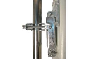
![]() BSAMNT-3 Wide Profile Antenna Downtilt Mounting Kit for 2.4 - 4.5 in (60 - 115 mm) OD round members. Kit contains one scissor top bracket set and one bottom bracket set.
BSAMNT-3 Wide Profile Antenna Downtilt Mounting Kit for 2.4 - 4.5 in (60 - 115 mm) OD round members. Kit contains one scissor top bracket set and one bottom bracket set.
Structural Support, Tools & Accessories
-
![]() BSAMNT-3 Wide Profile Antenna Downtilt Mounting Kit for 2.4 - 4.5 in (60 - 115 mm) OD round members. Kit contains one scissor top bracket set and one bottom bracket set.
BSAMNT-3 Wide Profile Antenna Downtilt Mounting Kit for 2.4 - 4.5 in (60 - 115 mm) OD round members. Kit contains one scissor top bracket set and one bottom bracket set.
Related Products
Antennas
-
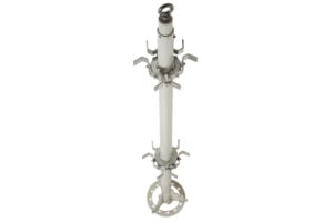
![]() 800PIPEKIT-X Cluster Mounting Kit. Use for mounting multiple wide panel antennas to a single pole or stand. One kit mounts up to three antennas. Removeable spacers allow this kit to fit on poles measuring 3.5, 4.5 or 5.5 in. OD.
800PIPEKIT-X Cluster Mounting Kit. Use for mounting multiple wide panel antennas to a single pole or stand. One kit mounts up to three antennas. Removeable spacers allow this kit to fit on poles measuring 3.5, 4.5 or 5.5 in. OD.
-
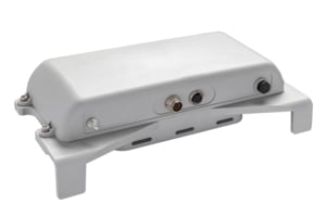
![]() APS-XT Antenna Orientation and Location Sensing System
APS-XT Antenna Orientation and Location Sensing System
Structural Support, Tools & Accessories
-
![]() 800PIPEKIT-X Cluster Mounting Kit. Use for mounting multiple wide panel antennas to a single pole or stand. One kit mounts up to three antennas. Removeable spacers allow this kit to fit on poles measuring 3.5, 4.5 or 5.5 in. OD.
800PIPEKIT-X Cluster Mounting Kit. Use for mounting multiple wide panel antennas to a single pole or stand. One kit mounts up to three antennas. Removeable spacers allow this kit to fit on poles measuring 3.5, 4.5 or 5.5 in. OD.
-
![]() 800PIPEKIT-X Cluster Mounting Kit. Use for mounting multiple wide panel antennas to a single pole or stand. One kit mounts up to three antennas. Removeable spacers allow this kit to fit on poles measuring 3.5, 4.5 or 5.5 in. OD.
800PIPEKIT-X Cluster Mounting Kit. Use for mounting multiple wide panel antennas to a single pole or stand. One kit mounts up to three antennas. Removeable spacers allow this kit to fit on poles measuring 3.5, 4.5 or 5.5 in. OD.
Included Products
Antennas
-
![]() BSAMNT-3 Wide Profile Antenna Downtilt Mounting Kit for 2.4 - 4.5 in (60 - 115 mm) OD round members. Kit contains one scissor top bracket set and one bottom bracket set.
BSAMNT-3 Wide Profile Antenna Downtilt Mounting Kit for 2.4 - 4.5 in (60 - 115 mm) OD round members. Kit contains one scissor top bracket set and one bottom bracket set.
Structural Support, Tools & Accessories
-
![]() BSAMNT-3 Wide Profile Antenna Downtilt Mounting Kit for 2.4 - 4.5 in (60 - 115 mm) OD round members. Kit contains one scissor top bracket set and one bottom bracket set.
BSAMNT-3 Wide Profile Antenna Downtilt Mounting Kit for 2.4 - 4.5 in (60 - 115 mm) OD round members. Kit contains one scissor top bracket set and one bottom bracket set.
Related Products
Antennas
-
![]() 800PIPEKIT-X Cluster Mounting Kit. Use for mounting multiple wide panel antennas to a single pole or stand. One kit mounts up to three antennas. Removeable spacers allow this kit to fit on poles measuring 3.5, 4.5 or 5.5 in. OD.
800PIPEKIT-X Cluster Mounting Kit. Use for mounting multiple wide panel antennas to a single pole or stand. One kit mounts up to three antennas. Removeable spacers allow this kit to fit on poles measuring 3.5, 4.5 or 5.5 in. OD.
-
![]() APS-XT Antenna Orientation and Location Sensing System
APS-XT Antenna Orientation and Location Sensing System
Structural Support, Tools & Accessories
-
![]() 800PIPEKIT-X Cluster Mounting Kit. Use for mounting multiple wide panel antennas to a single pole or stand. One kit mounts up to three antennas. Removeable spacers allow this kit to fit on poles measuring 3.5, 4.5 or 5.5 in. OD.
800PIPEKIT-X Cluster Mounting Kit. Use for mounting multiple wide panel antennas to a single pole or stand. One kit mounts up to three antennas. Removeable spacers allow this kit to fit on poles measuring 3.5, 4.5 or 5.5 in. OD.
-
![]() 800PIPEKIT-X Cluster Mounting Kit. Use for mounting multiple wide panel antennas to a single pole or stand. One kit mounts up to three antennas. Removeable spacers allow this kit to fit on poles measuring 3.5, 4.5 or 5.5 in. OD.
800PIPEKIT-X Cluster Mounting Kit. Use for mounting multiple wide panel antennas to a single pole or stand. One kit mounts up to three antennas. Removeable spacers allow this kit to fit on poles measuring 3.5, 4.5 or 5.5 in. OD.
Other Ways to Browse
